MODELING OF SUNSEEKER PREDATOR 108 YACHT ON SOLIDWORKS
MODELING OF SUNSEEKER PREDATOR 108 YACHT ON SOLIDWORKS
OBJECTIVES:
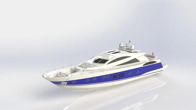
The objective of the project is to design and assemble all the parts of the predator 108 yacht and to create a photo-realistic rendering of the yacht. To learn SolidWorks software in an industrial approach. To learn different commands and complex surface features and solid features within the solid works.
INTRODUCTION:
The sunseeker predator 108 is a luxury motor yacht it has a fiberglass hull, and it is powered by MTU engines of 2000hp each giving a maximum speed of 45 knots and a cruising speed of 35 knots.
In this project sunseeker predator 108 yacht entire components modeling was done on Solidworks and Solidworks visualize.
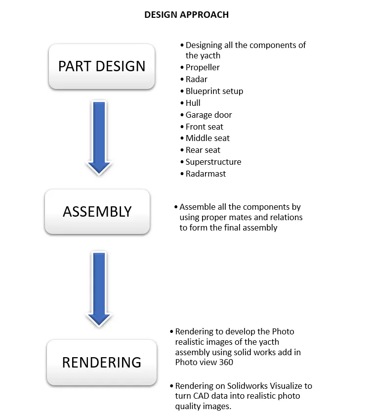
The following are the key part components of the yacht we deal with are:
- Propeller
- Radar
- Blueprint setup
- Hull
- Garage door
- Front seat
- Middle seat
- Rear seat
- Superstructure
- Radar mast
After designing the parts, we assembly using Solidworks. The final model was rendered in photo view 360 on Solidworks and Solidworks visualize.
ENGINEERING DESIGN PROCESS:
1. Define the problem
2. Do Background research
3. Specify Requirements
4. Brainstorm, Evaluate, and choose the solution
5. Develop and prototype solution
6. Test solution
7. Solution meets requirements. Partially or not at all
8. Communicate results
9. Based on results and data, make design changes, prototype, test again, and review new data.
SURFACE MODELLING:
Surface modeling is a method of creating planar or non-planar complex geometry which has cerate models of complex shapes we can convert models into solid models. we can also extract a surface from the solid model using the tools available for surface modeling.
Surface commands and features used while modeling the yacht:
All the images shown in the following feature commands are used as examples,
- Extrude surfaces- Extrude a sketch or selected sketch contours in one or two directions to create a surface feature.
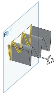
- Lofted surface – Create a lofted surface between two or more profiles or sketches. Specify start and end constraints and add guide curves to control the path shape.
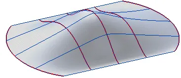
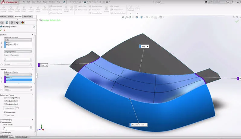
- Boundary surface-The boundary surface feature lets you create surfaces that can be tangent or curvature continuous in both directions (all sides of the surface). In most cases, this delivers a higher quality result than the loft tool.
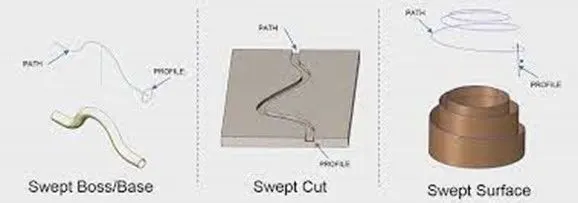
- Swept surfaces-it sweeps a closed profile along an open or closed path to create a surface feature. It uses a tangent plane at the end of the path so that the path is normal to the swept surface.
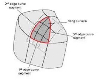
- Filled surfaces- patches a surface within a boundary defined by edges, sketches, or curves. We can use constraint curves to fill surfaces and adjust resolution control to improve surface finish.
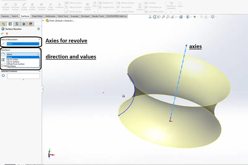
- Revolved surfaces- Revolve a sketch or selected sketch contours around an axis to create a surface feature.
- Ruled surfaces- inserts ruled surface in a specified direction from edges. Tangent to the surface, tapered to vector, perpendicular to vector, or sweep can be selected. We can also trim and knit the surfaces and remove any connecting surfaces.
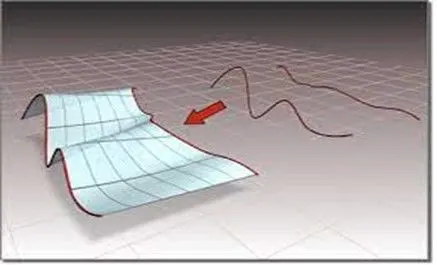
- Trim surfaces- it trims the surfaces where a surface intersects with another surface, plane, or sketch.
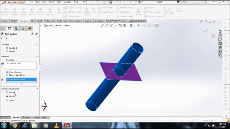
- Offset surface- offsets surfaces using one or more contiguous faces this tool helps us to create an offset surface with gaps.
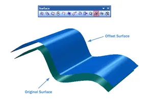
- Knit surface- it combines two or more adjacent, non-intersecting surfaces into a single surface body. The surfaces must joint at an edge. If the resulting knit surfaces enclose a volume, we can create a solid body from the property manager.
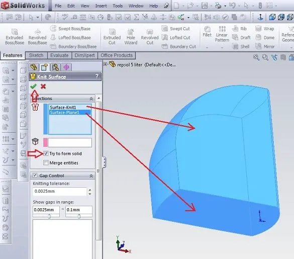
- Extend surface- extends one or more edges or faces on a surface, based on end conditions and extension type.
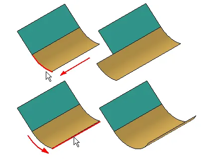
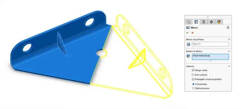
- Mirror surfaces- mirror feature is a copy of selected features mirrored about a plane or planar face. A mirror sketch entity is a copy of a selected sketch entity that is mirrored about a centreline. If the original feature or sketch is modified, the mirrored copy is updated to reflect the change.
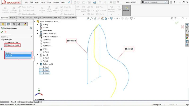
- Projected curve-a projected curve is typically used either in sweeps and lofts as a path or guide curve there are two types of projected curves.
- Sketch on the sketch: use two sketches to make a single curve.
- Sketch on the surface: use a sketch to project on a surface.
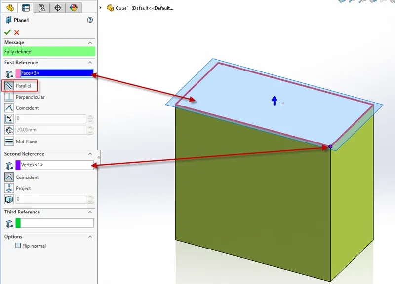
- Reference plane-we can create planes in part or assembly documents we can use planes to sketch to create a section view of a model for a neutral plane in a draft feature and so on.
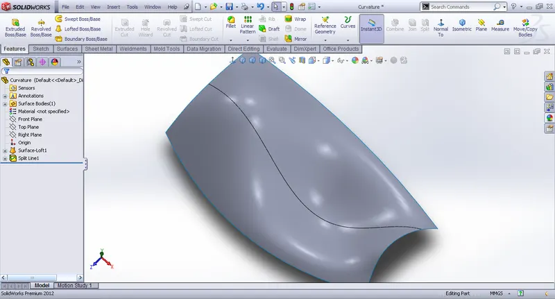
- Split line-The split line tool projects an entity (sketch, solid, surface, phase, plane, or surface spline) two surfaces are curved or planner surfaces. it divides a selected face into multiple separate faces we can split curves on multiple bodies with one command
- Split entity-we can split a sketch entity to create two sketch entities. conversely, we can delete a split point to combine sketch entities into a single sketch entity.
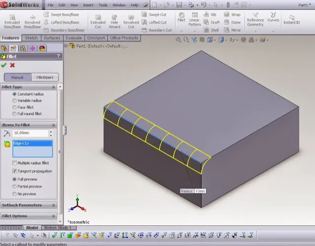
- Fillet- filet is an internal rounding of a corner or edge in a sketch or an edge on a surface.to smoothen the sharp edges.
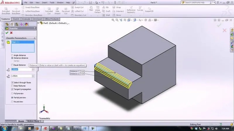
- Chamfer-chamfer tool creates a beveled feature on selected edges, faces, or a vertex.
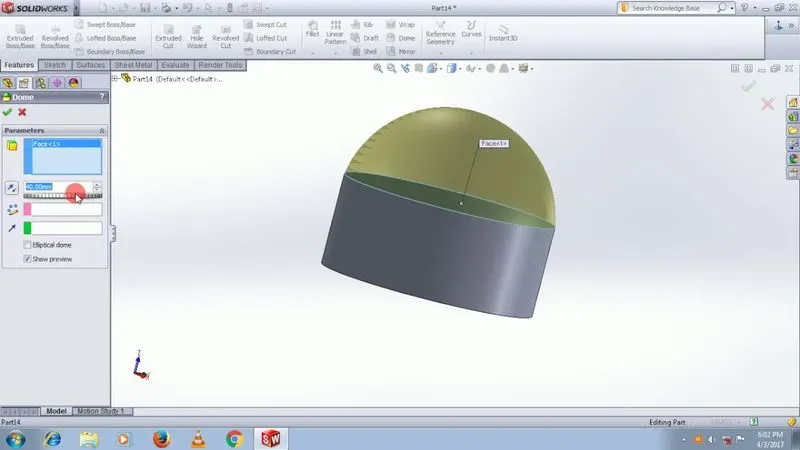
Dome- it can add one or more domes to the selected planar are non-planar faces. The software calculates the distance using the radius of the arc as basic of the dome
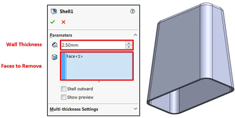
Shell-it Is used to create the thickness of the profile.
1. PART DESIGN:
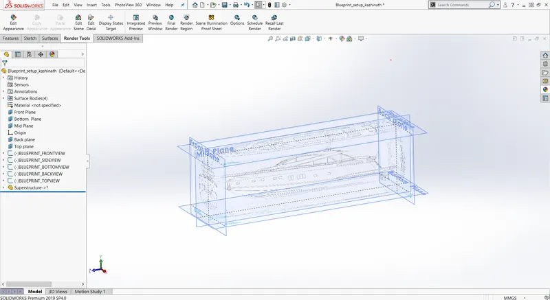
Blueprint setup: Blueprint is basically a plan (as in serving as a model or providing guidance). Blueprint is a technical drawing of different orthographic views of a product. modeling is done by matching the exact same sketch picture of the blueprint to develop the final model. It also ensures the accuracy and the proportion of the product designing the product without using the blueprint may lead to errors, in dimensions and unnatural proportions.
Fig, shows the blueprint setup in the solid works
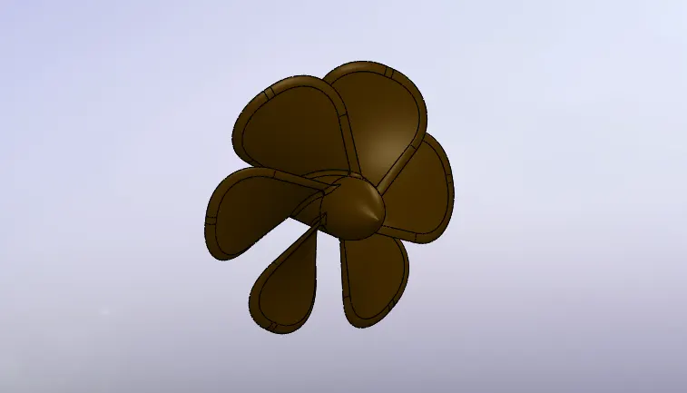
1. Propeller: The purpose of the propeller is to provide a method of propulsion by converting the rotational motion into thrust, so the yacht can move forward through the water. The propeller itself consists of two or more blades connected by a central hub that attaches the blades to the engine shaft in this yacht we used 3 propellers.
The Sketch commands used while modeling the propeller:
- Line
- Circle
- Spline
The Sketch commands used while modeling the propeller:
- Cut extrude
- Revolve boss/base
- Reference plane
- Circular pattern
- Fillet
- Loft
2. RADAR: It is a detection system that uses radio waves to determine the distance (range), angle, or velocity of objects. It can be used to detect, ships, aircraft, spacecraft. A radar system consists of a transmitter producing electromagnetic waves in the radio or microwaves domain, a transmitting antenna, a receiving antenna (often the same antenna is used for transmitting and receiving), and a receiver and processor to determine the properties of the object.
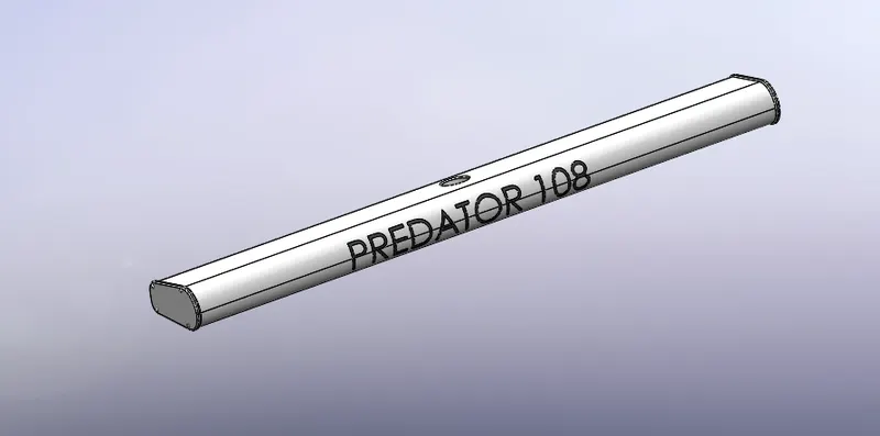
The Sketch commands used while modeling the radar:
- line
- circle
- spline
- Text
The features command used while modeling the radar:
- Extruded cut
- Reference plane
- Mirror
- Shell
- Fillet
3. hull: The hull is the main part of the yacht. A hull is the watertight body of a ship, boat, or flying boat. It holds the other components of the yacht The hull may open at the top (such as a dinghy), or it may be fully or partially covered with a deck. The line where the hull meets the water surface is called the waterline.
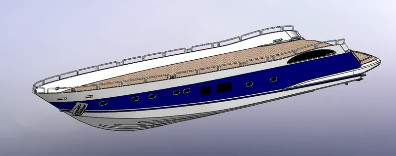
The Sketch commands used while modeling the hull:
- Sketch picture
- line
- Spline
- Rectangle
- Arc
- Circle
- 3-D Sketch
- Slot
The features command used while modeling the hull:
- Bose Extrude
- Cut Extrude
- Project curve
- Chamfer
- Fillets
- Delete face
- Split
- Mirror
- Reference plane
- Shell
The surface commands used while modeling the hull:
- Reference plane
- Revolved surface
- Extended surface
- Projected curve
- Surface loft
- Surface trim
- Surface extrude
- Surface fill
- Surface knit
4. Garage door: garage door is a door that is present in the back of the hull that opens manually or by an electric motor. It accommodates automobiles and other vehicles like cars, bikes, etc.
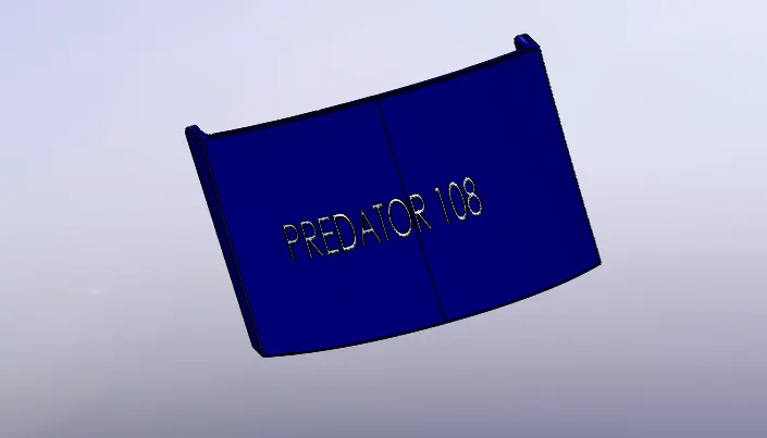
The Sketch commands used while modeling the Garage door:
- Line
- Spline
- Circle
- Text
The feature commands used for modeling Garage door:
- Extrude cut
- Reference place
- Fillet
- Shell
- Mirror
5. Front seat: front seat is the seat at the front part of the yacht they have a built-in storage unit underneath them. the front seat in our model was placed before the superstructure and it has seats to rest on it and to get more comfortable.
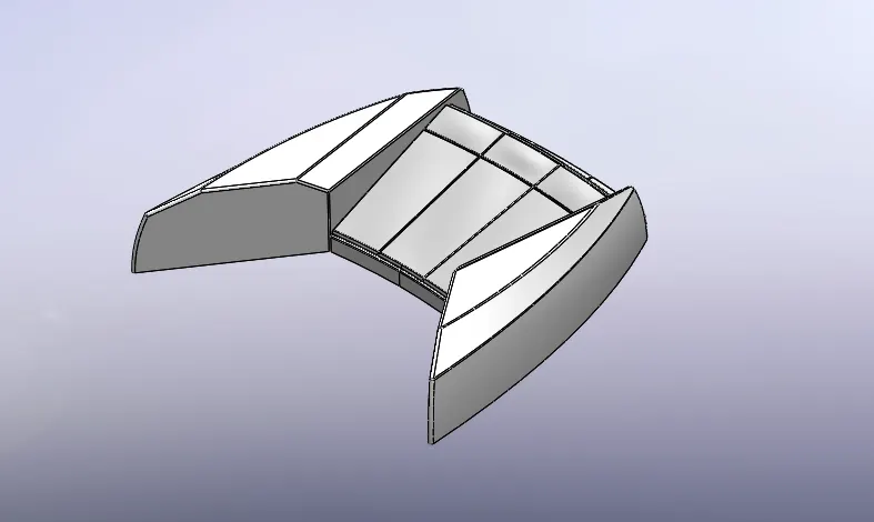
The Sketch commands used while modeling the front seat:
- Sketch picture
- Line
- Spline
- Circle
- Arcs
The surface commands used while modeling the front seat:
- Extruded surface
- Lofted surface
- Filled surface
- Offset surfaces
- Extend surfaces
- Trim surface
- Knit surface
- Swept surface
- Revolved surface
The Features command used while modeling front seat:
- Extruded cut
- Revolved boss
- Fillet
- Chamfer
- Mirror
- Dome
6. Middle seat: Middle seat is designed on the deck surface of the hull. Middle Seat is designed in U shape and it has a table in the middle this part is created by using only sketch commands, solid features blueprint sketch is taken into consideration for the dimensions and views while modeling the middle seat.
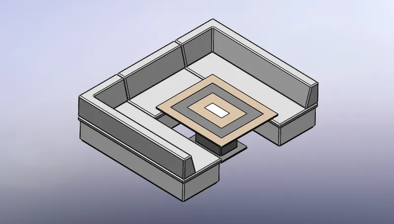
The Sketch commands used while modeling the middle seat:
- Sketch picture
- Line
- Rectangle
The Features commands used while modeling middle seat:
- Boss/Base extrude
- Fillet
- Chamfer
- Reference plane
- Mirror
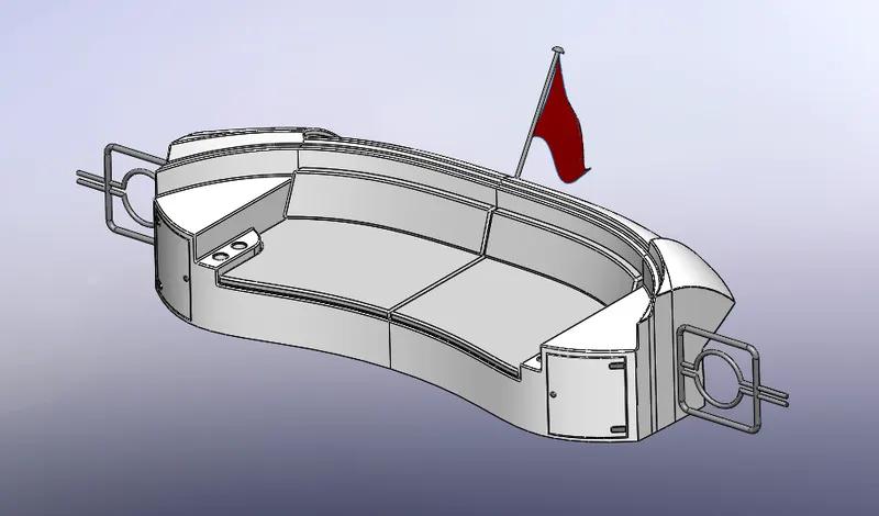
7. Rear seat: Rear seat is also placed on the deck of the hull behind the superstructure over the garage door. It contains two storage units. It was designed by importing the deck surface of the hull as interface surface and also taken the guidance of the blueprint sketch.
The Sketch commands used while modeling the Rear seat:
- Sketch picture
- Line
- Spline
- Circle
- Arcs
- Rectangle
The surface commands used while modeling the Rear seat:
- Extrude surface
- Offset surface
- Filled surface
- Swept surface
- Knit surface
- Ruled surface
- Lofted surface
- Trim surface
- Extend surface
The Features commands used while modeling Rear seat:
- Extruded boss/base
- Revolved boss/base
- Reference plane
- Fillet
- Mirror
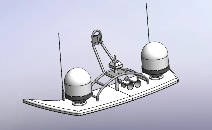
8. Radar Mast: is an electronic navigation instrument that uses a rotating antenna to sweep a narrow beam of microwaves around the water surface surrounding the yacht to the horizon. Radar mast is mounted above the superstructure, and it holds the necessary types of equipment such as navigation lights, horns, radars.
The Sketch commands used while modeling Radar mast:
- Sketch picture
- Line
- Spline
- Rectangle
- Circle
- Arcs
The Features commands used while modeling Radar mast:
- Lofted boss/base
- Revolved boss/base
- Extrude boss/base
- Swept boss/base
- Projected curve
- Reference plane
- Fillet
- Dome
- Shell
- Mirror
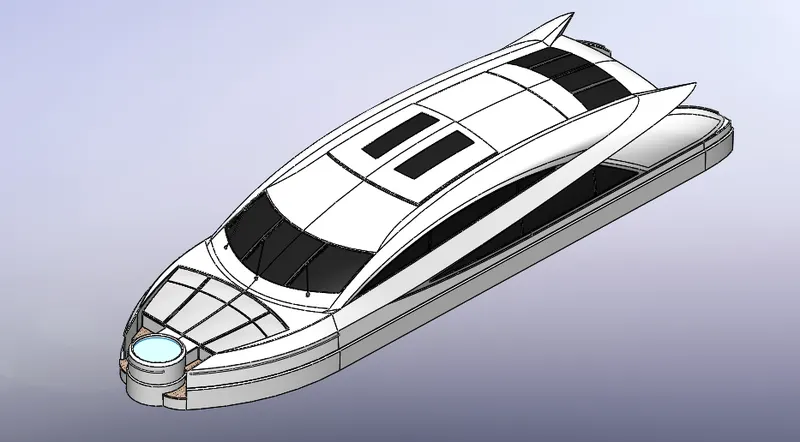
9. Superstructure: superstructure is an extended construction of any building or platform that rises above the rest of the building or platform in a distinct manner.
Thus, superstructure means adding construction to an already existing structure. In ships, this is the name given to the part of the ship that emerges from the deck. The superstructure is mostly designed in fashion as well. This is because it is the most easily visible part of the ship, in fact, it is the identification of the ship, and so the designers try to provide it with an identity that is unique.
The Sketch commands used while modeling the superstructure:
- Sketch picture
- 3d sketch
- Line
- Arc
- Spline
- Circle
- Rectangle
The surface commands used while modeling the superstructure:
- Extrude surface
- Offset surface
- Filled surface
- Swept surface
- Knit surface
- Ruled surface
- Lofted surface
- Trim surface
- Extend surface
The Features commands used while modeling the superstructure:
- Reference curve
- Project curve
- Convert entities
- Split
- Split line
- Fillet
- Mirror
- Chamfer
2. ASSEMBLY:
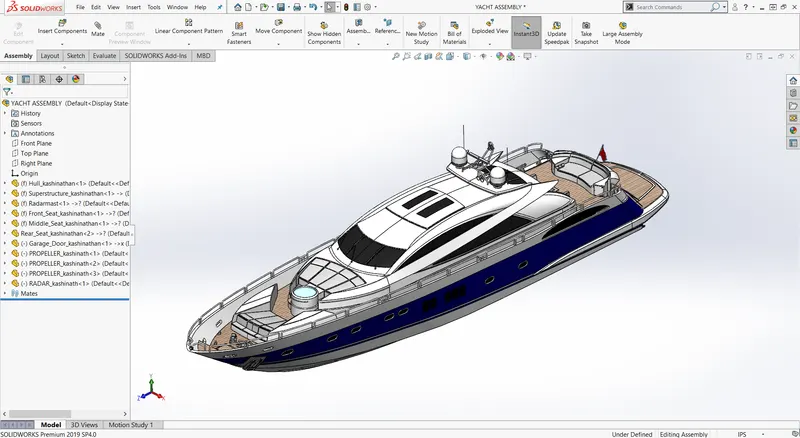
The term assembly is most often referred to as putting components together in an assembly line, but more specifically it refers to creating a complete product that performs an intended function.
Adding a component to an assembly creates a link/mate between the assembly and the component by applying the proper mates and links to the components are assembled. Changes in the components are automatically reflected in the assembly.
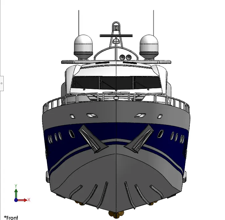
FRONT VIEW OF THE YACHT
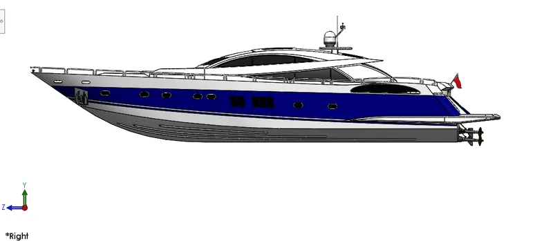
RIGHT VIEW OF THE YACHT
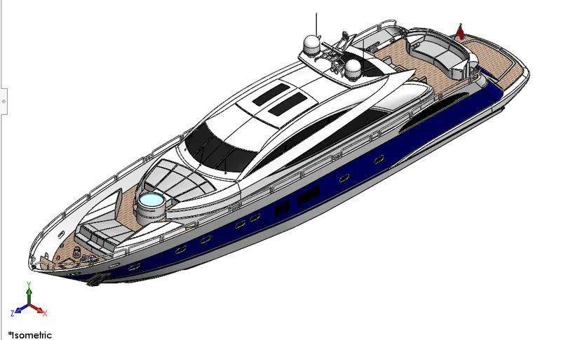
ISOMETRIC VIEW OF THE YACHT
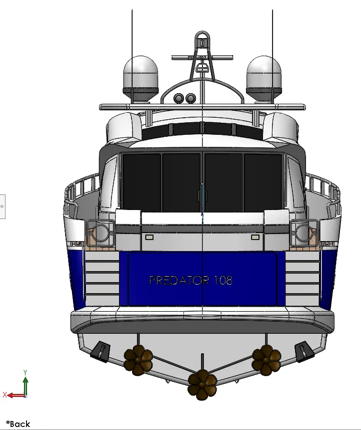
BACK VIEW OF THE YACHT
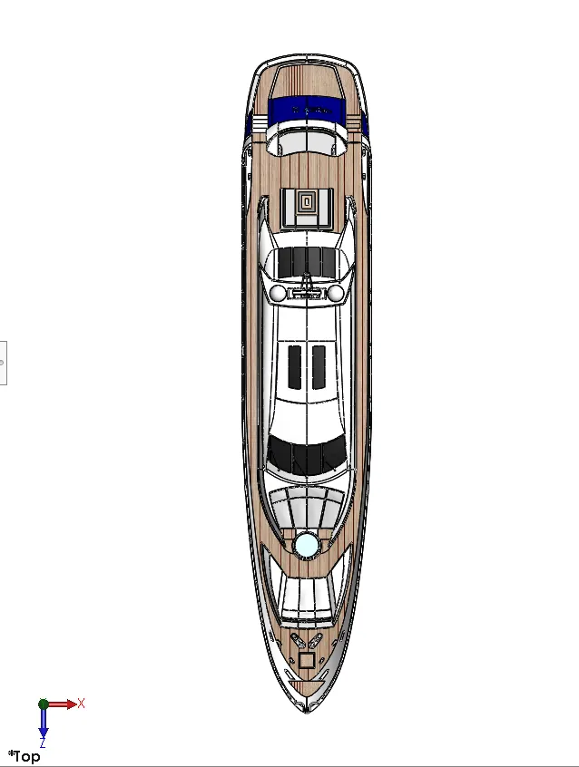
TOP VIEW OF THE YACHT
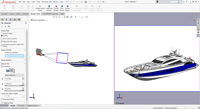
CAMERA SETUP VIEW OF THE YACHT
3. RENDERING:
RENDERING IN PHOTO VIEW 360:
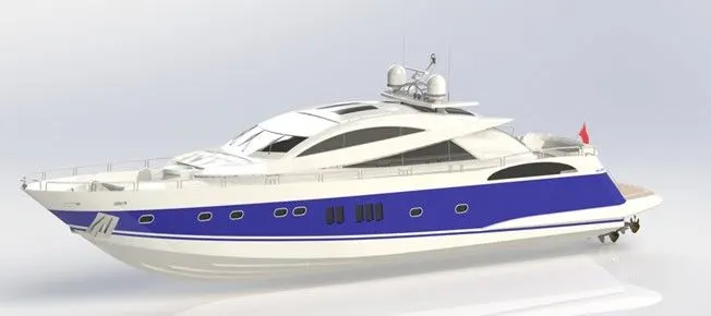
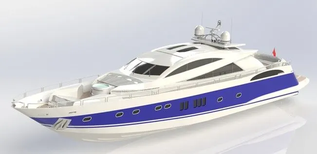
Photo view 360 is a Solidworks add-in that produces photo-realistic renderings of the models. The rendered images incorporate the appearance, lighting, scene, and decals included with the model.
- With a model open, click Tools > Add-In and add in Photo View 360.
- Start a preview in the graphics area or open the Preview window to see how changes you make to the model affect the rendering.
- Edit appearances, the scene, and decals.
- Edit lights.
- Edit Photo View Options.
RENDERING IN SOLIDWORKS VISUALIZE:
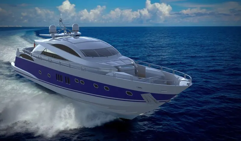
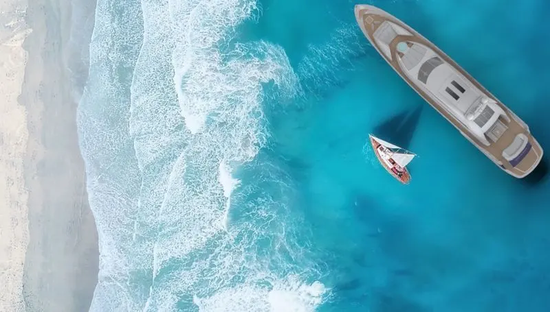
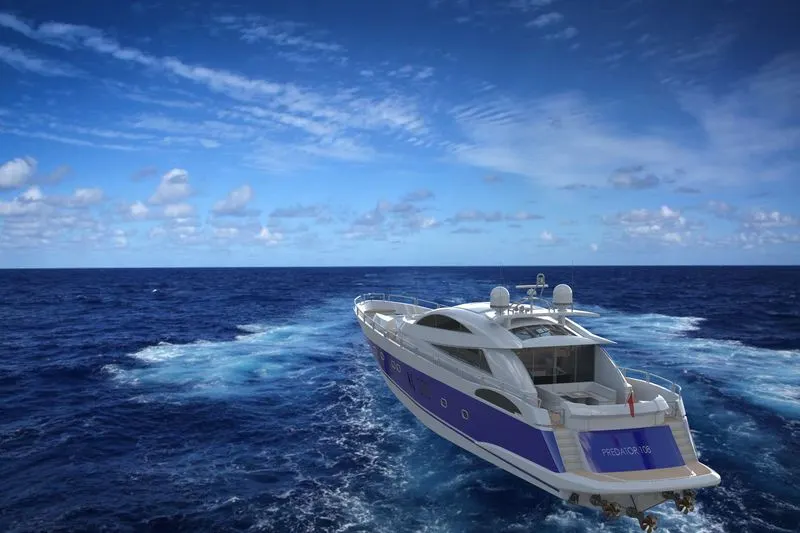
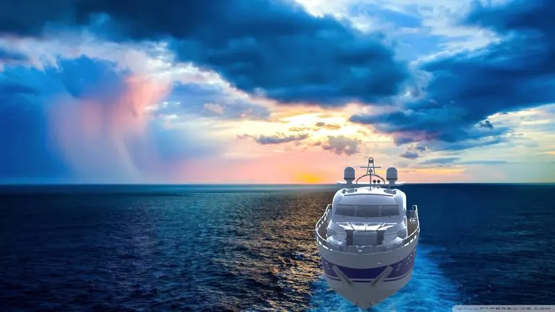
SOLIDWORKS Visualize allows you to leverage your 3D CAD data to create photo-quality content in the fastest and easiest way you can–from images to animations and immersive virtual reality.

CONCLUSION: The design, assembly, rendering, of the sunseeker predator 108 Yacht was successfully done using Solidworks and Solidworks visualize. This project helped to enhances my skills in surface modeling and product design. By completing this project, it has given me insight into marine vehicle design.