MODELING OF AMERICAN CHOPPER ON SOLIDWORKS AND PHOTO REALISTIC RENDERING
MODELING OF AMERICAN CHOPPER ON SOLIDWORKS
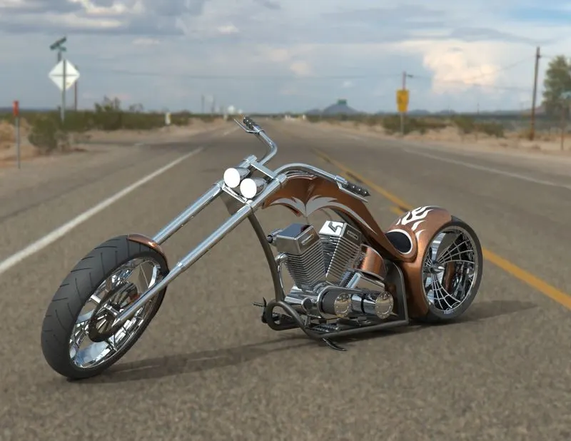
Objective:
This project aims to build the complete cad modeling of motorcycle parts and assemble the parts of an American chopper using Solidworks and creating a photo-realistic rendering by Solidworks Visualize/photo view 360.
Introduction:
In this project, I performed the entire modeling of an American chopper on solid works and solid works visualize to create a modeling and photorealistic rendering of American chopper by using Solidworks.
The different components of the motorcycle we deal with are:
- Chassis
- Engine with exhaust system
- Chain and transmission belt
- Oil Tank
- Kickstand and foot pedals
- Front-wheel and Rear wheel with rims sprockets and calipers
- Front fork along with handlebars and grips
- Front and Rear Fenders
Components of the chopper:
- Transmission belt
- Kickstand
- Front fender
- Rear fender
- Chain
- Oil tank
- Pedal
- Front-wheel
- Rear-wheel
- Front fork
- Chassis
- Engine
- Gas tank
The parts are designed separately and finally assembled to get a photo-realistic rendering of an American chopper.
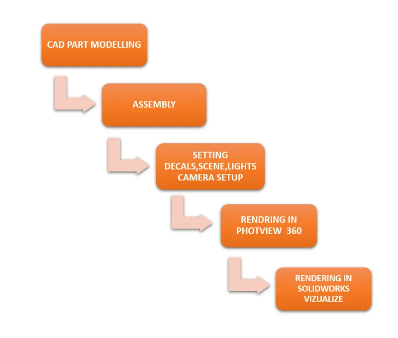
DESIGN APPROACH PROCESS FLOW CHART
Features and properties used in the entire model to design different parts:
Design Method Before design the model, it is helpful to plan out a method of how to create the model. After identifying needs and isolate the appropriate concepts, you can develop the model:
Sketches: Create the sketches and decide how to dimension and where to apply relations.
Features: Sketches Select the appropriate features, such as extrudes, revolve, and fillets, determine the best features to apply, and decide in what order to apply those features.
Assemblies: Select the components to mate and the types of mates to apply.
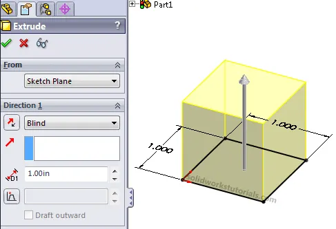
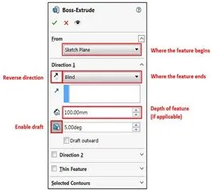
1. Extrude Boss: The Extruded Boss is the most basic of all SOLIDWORKS features and extrudes a sketch along a straight-line path to add material. Click in the graphics area to establish the direction of the extrusion. The Base-Extrude Property Manager appears. Edit the properties in the Base Extrude Property Manager. Extrude tool to create a 3D base feature. This feature is used in most of the components in American.
2. FILLET: Fillets serve to round off sharp edges and or corners by adding or removing material, depending on whether the edge is internal or external. Fillets are applied features, not sketch features. This means that fillets do not require you to create a sketch. Instead, you select the edges of an existing feature, set the fillet radius, and create the fillet. As you increase the radius, the edges or faces become rounder.
To create fillets:
- Click Fillet on the Features toolbar, or click Insert, Features, Fillet/Round.
- Set the Property Manager options. For constant radius fillets only, you can use the Fillet Xpert to add or modify fillets and to manage fillet corners.
- Click OK.
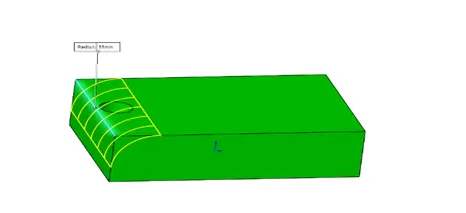
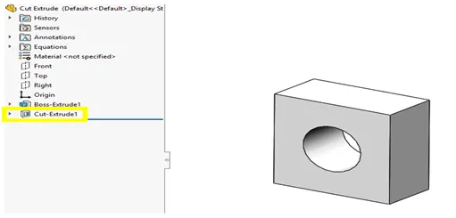
3. Extrude Cut: The Cut-Extrude tool is similar to an extrude feature, except that it removes material from the model instead of adding material. You can use open or closed sections to create a cut. Removing material using a closed section creates a slot to create a cut, use the same depth options as for extruded protrusions.
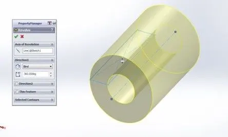
4. Revolved Boss Feature: tool which is used to create a solid 3D model around an axis. You can resolve the sketch around an axis to add materials to it. It is very important to draw an axis in the sketch which needs to be revolved. A revolved feature is an axisymmetric shape that is created by revolving an open or closed section view by a specified angle around a central axis.
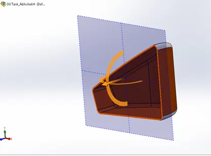
5. Shell: The Shell feature hollows out the inside of the solid, leaving a shell of a specified wall thickness. It lets you specify a surface or surfaces that you want to remove from the shell. takes a solid and turns it into a thin-walled feature.
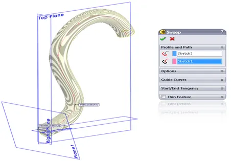
6. Sweep Boss / Sweep Cut: Tool that creates a solid, cut, or surface feature by moving a profile along a path. To create a solid, use the Swept Boss tool to move a profile along a path. The profile can contain one or more closed contours.
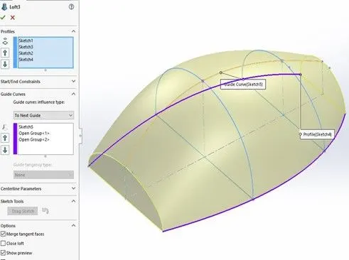
7. Loft Boss/ Loft Cut: A loft cut is a features tool that helps to cut or remove materials between two or more profiles. It is just like Loft Boss or Base tool, but the main difference is that the Boss feature is used to add material between profiles, and Loft cut used to remove materials between them.
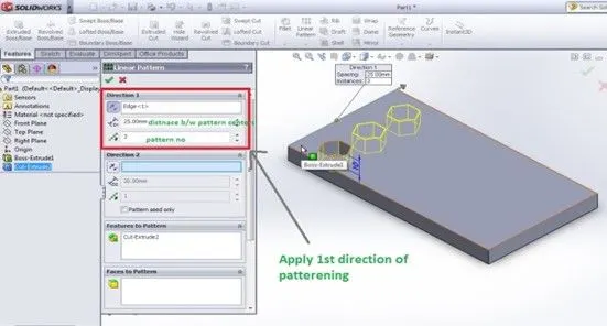
8. linear pattern: linear pattern features tool is used to create patterns of features linearly for linear patterning there is a parent pattern used to create the array of patterns in one or two dimensions.
The patterns should follow the exact shape of the main pattern if any changes in dimension later it automatically updates to other pattern shapes produced from the base pattern.
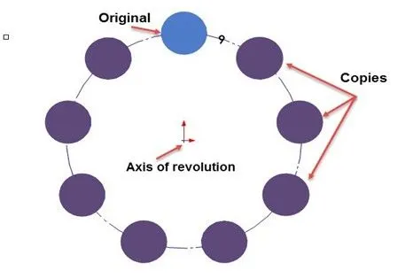
9. Circular patterns: To create copies of objects arranged in a pattern both easier and faster. circular patterns to create multiple instances of one or more features that you can space uniformly around an axis.
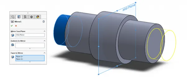
10. Mirror: Mirroring is another way that SolidWorks can create a “copy” of an existing object. Additionally, one must choose a plane to mirror parts.
Here is a quick example of what a mirror does. (The plane in between the mirrored parts is the center of the parts)
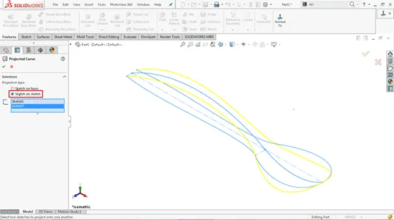
11. Projected curve: A sketched curve onto a model face to create a 3D curve that represents the intersection of two extruded surfaces generated by creating sketches on two intersecting planes. You can create multiple closed or open-contour projected curves from a single sketch. You can also use 3D sketches as input for the Projected Curve tool.
Terminology:
These terms appear throughout the SOLIDWORKS software.
1. Origin: Appears as two blue arrows and represents the (0,0,0) coordinate of the model. When a sketch is active, a sketch origin appears in red and represents the (0,0,0) coordinate of the sketch. You can add dimensions and relations to a model origin, but not to a sketch origin.
2. Plane: Flat construction geometry. You can use planes for adding a 2D sketch, section view of a model, or a neutral plane in a draft feature, for example.
3. Axis: Straight line used to create model geometry, features, or patterns. You can create an axis in different ways, including intersecting two planes.
4. Face: Boundaries that help define the shape of a model or a surface. A face is a selectable area (planar or nonplanar) of a model or surface. For example, a rectangular solid has six faces.
5. Edge: Location where two or more faces intersect and are joined together. You can select edges for sketching and dimensioning, for example.
6. Vertex: Point at which two or more lines or edges intersect. You can select vertices for sketching and dimensioning, for example.
Now let us see the application of the tools/features used in the American chopper components that we have built.
PART MODELLING:
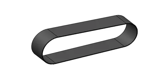
1. TRANSMISSION BELT: Belts are mechanical elements used for power transmission without phase shift.to efficiently transmit power or movement.
Tools/Features used while designing the transmission belt: line, 3point arc, offset tool, Fillet, Extrude boss feature. It is a single extruded surface whose outer edge has been filleted by giving a desired dimension and relations to make a fully defined sketch. The appearance used is matte rubber.
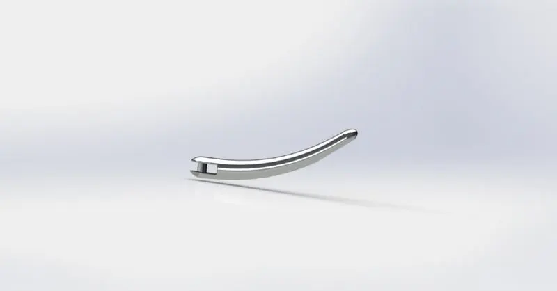
2. KICKSTAND: metal rod attached to a bicycle or motorcycle, lying horizontally when not in use, that may be kicked into a vertical position to support the vehicle when it is stationary
Tools/Features used while designing the kickstand: Ellipse, Spline, Pierce relation, loft, cut extrude, Fillet, Dome, Split feature
Designing the kickstand Cut extrude features to create mounting and Fillet features to make the sharp edge smooth and used Dome features. Split feature to create a flat surface on the bottom which will touch on the ground.
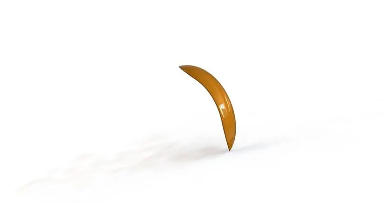
3. FRONT FENDER: front fenders and rear fenders are both parts used to protect your feet and ankles from spray being thrown into the air by moving tires. And it also enhances the looks of the motorcycle.
Tools/Features used while designing the front fenders: 3point arc, offset, construction line, Revolve boss, split tool, fillet, shell. The appearance used is metallic paint, Siena.
Revolve boss feature with selecting construction line as an axis of revolution for specific angle in both directions. split tool to cut the part and the outer edge of the fender is the fillet.
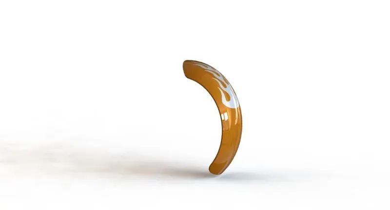
4. REAR FENDER: The same method has been applied in the rear fender as it was in the front fender. the only difference between the two is the sizes of both the fenders which vary accordingly with the size of the tire.
Tools/Features used while designing the rear fender: Cut extrude, revolve, fillet, chamfer, combine, circular pattern. The appearance used is metallic paint Siena and applied decals.
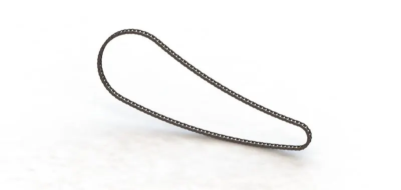
5. CHAIN: chain is a part of a motorcycle it is used to convey power to the wheels of a vehicle. The power is conveyed by the roller chain known as the transmission chain, passing over a sprocket gear with the teeth of the gear meshing with the holes in the links of the chain.
Tools/Features used while designing the chain: boss extrudes, curve-driven pattern, mirror. Appearance used finely finished chrome-plated metal.
To model chain Sketched the path of the front plane and then created two blocks inner and outer plate of the chain-link using the boss extrude features and save it to use it later and then simultaneously applied with a concentric relation to one joint of the path calculatedly we begin with the process of curve path arrangement from on joint of the path to another determining the angles and the number of blocks required using the curve driven pattern until the entire loop is completed finally. we mirror the face of the links to the pins concerning the midplane.
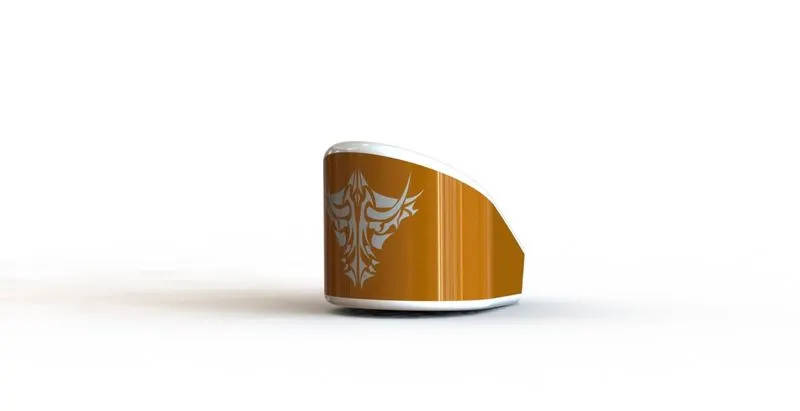
6. OIL TANK: oil storage tank is a container or reservoir that temporarily holds before it is used or consumed for lubrication and cooling.
Tools/Features used while designing the front fenders: extrude boss, combine, shell, fillet. Appearance used metallic paint, Siena.
The oil tank is sketched on the Top Plane and extruded boss above now to attain the structure of the oil tank one more sketch is made on the midplane extruded and combined and at last, a shell function is used to make the part hollow to create thin-walled features and the edges are made round by applying fillet.
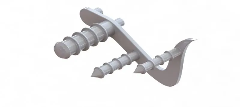
7. PEDAL: pedal is a part of the motorcycle used for rear brake and gear change lever by resting foot on the pedal.
Tools/Features used while designing the pedal: extrude boss, revolve boss, linear pattern, circular pattern dome, fillet, chamfer.
To model pedal sketch of the base pedal on the front plane and a circular hole for the footrest using the extruded boss is created with dimension. and the pins which are extruded the second time, revolve boss feature to make a 3d image the top of the rest is applied with a dome, and edges and joints are filleted to get a smooth finish. A circular pattern is extruded on each of the front-facing extrudes which are then arranged using a linear pattern and a fillet is applied to all the edges and the joints of the last pattern.
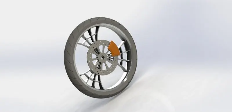
8. FRONT WHEEL: it is the part of the motorcycle which is made to cope with radial and axial forces to absorb shocks mounting other critical components such as brakes calipers, brake rotor, tire, rim.
Tools/Features used while designing the front wheel: revolve boss, extrude boss, cut extrude revolve cut, circular pattern, combine, chamfer, fillet. Appearances are applied individually.
To model the front wheel first we start with the rim used revolve boss to make a ring and then used the cut extrude to make hub after that used the extrude boss, revolve cut, circular pattern to make multiple instances of spider spokes. to make one solid body we used the combine feature. To make a Brake rotor used extrude boss to make a disc and used the circular pattern and cut extrude to eliminate the excess part. To model the brake caliper, To create a sketch on the rotor face used extrude boss features in both directions to avoid the sharp edges we apply the chamfer and fillet features. Finally, to create a tire we use convert entities for reference and create sketch use revolve boss feature and then using cut extrude features creating a tread on the surface of the tire.
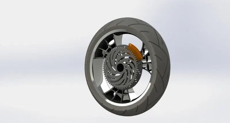
9. REAR WHEEL: The design of the rear wheel is similar to the front wheel the differences are in the size of the wheels. The rear wheel as one extra parts sprocket to create the sprocket extrude boss feature is used to disc and by sketching on the disc, we use extrude cut to make tooth profile and by using the circular pattern feature we create teeth of the sprocket.
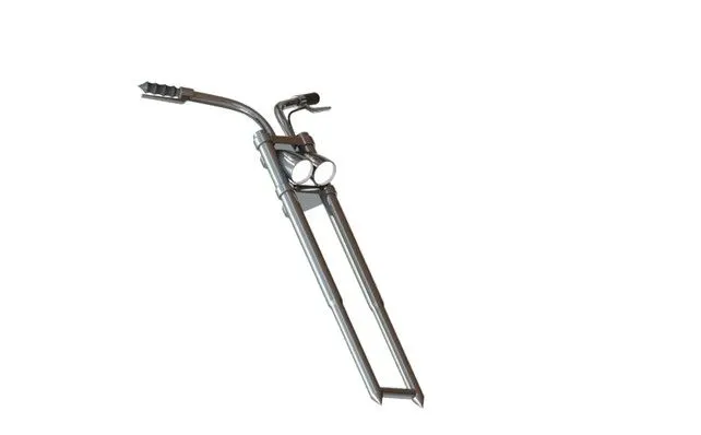
10. FRONT FORK: The front fork prevents excessive weight on the front wheel during drastic sudden applications the break, softens bumping when driving on rough road surfaces.
Tools/Features used while designing the front fork: revolve boss, extrude cut, extrude boss, projected curve, sweep boss, revolved cut, mirror, fillet. The appearance applied glossy chromium.
11. CHASSIS: All the components of a motorcycle, like the suspension, wheels, fuel tank, oil tank seats, handlebars, etc, are attached to this base structure which lends a motorcycle its strength and ability to handle well.
Tools/Features used while designing the chassis: projected curves, sweep boss, mirror, extrude cut, extrude boss, revolve boss, split, combine, fillet to eliminate the sharp edges. Applied appearance
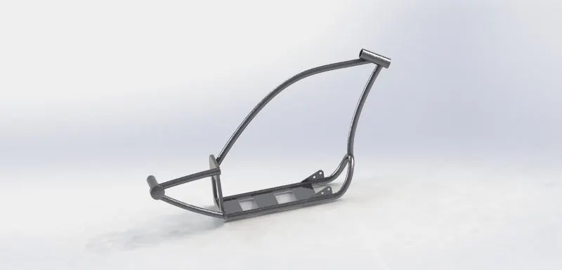
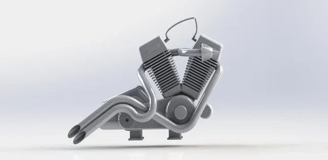
12. ENGINE: A machine for converting thermal energy into mechanical energy or power to produce force and motion. The engine is the vehicle’s main source of power.
Tools/Features used while designing the chassis: extrude boss, cut extrude, revolve boss, dome, chamfer, linear pattern, circular pattern, split, combine, fillet. Applied appearance chrome-plated metal.
To create an exhaust, we used a projected curve and composite curve to make a path of the exhaust pipes. all the edges are filleted to attain the shape.
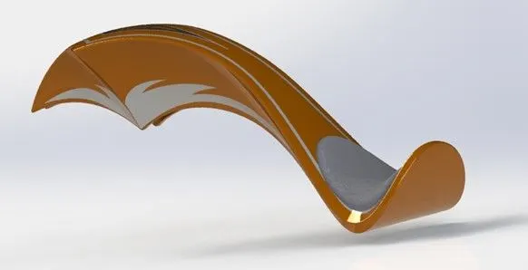
13. GAS TANK: A fuel tank is a safe container for flammable fluids holding the fuel supply in a motor vehicle. in which the fuel is propelled or released into an engine.
Tools/Features used while designing the gas tank: projected curve, surface loft, boundary surface, surface knit, fillet, surface extrude, sweep cut, shell to create a thin-walled surface or hollow surface. Appearance applied sienna to the part and grey cotton material is used for the seat.
surface sweep to attain the basic layout of the gas tank. Surface knit is to create gas tanks outer surface. split, surface extrude, fillet features are used to create a seat. Boundary surface, lofted surface, and surface knit features are used to create a body of the gas tank. Sweep cut, shell, and fillet features are used to complete the model gas tank.
ASSEMBLY:
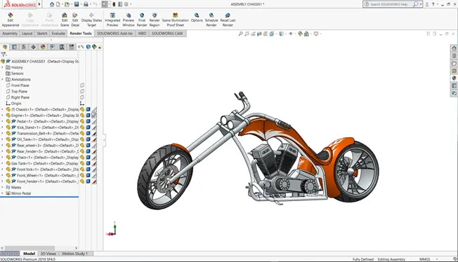
After making all the parts to assemble the entire American chopper, we begin by bringing in the chassis first and using its plane and geometry as a base for the entire solid assembly. Followed by, engine, pedal, kickstand, transmission belt, oil tank, rear wheel, rear fender, chain, gas tank, front fork.
The engine part is matted coincident with the base of the chassis then the planes of the engines are mated so it is a fixed body and doesn’t move at last a distance mate is applied so that the part is fully defined Followed by, kickstand, transmission belt, oil tank, rear wheel, rear fender, chain, gas tank, front fork
The mirror features are used to mirror the pedal to the other side of the chopper. Finally, the front wheel is attached with the front fork as it was attached in the case of the rear wheel and the fender is placed above the front wheel.
To make a fully defined assembly, we applied mates such as to coincide, concentric, parallel, distance, tangent, and advanced mates such as width and limit angle mate. By applying the limit angle mate, we can rotate the kickstand towards the ground when the motorcycle is stationary this mate gives some realistic looks to the American chopper.
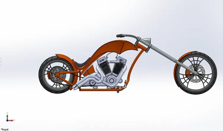
FRONT VIEW
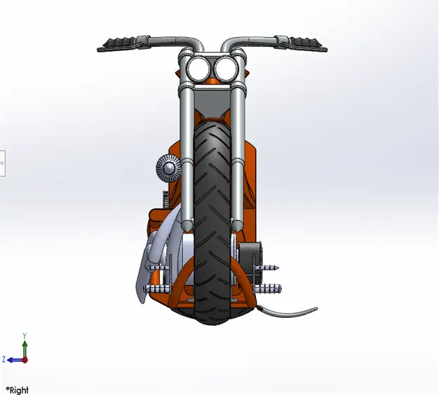
RIGHT VIEW
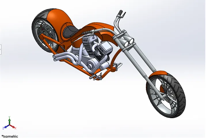
ISOMETRIC VIEW
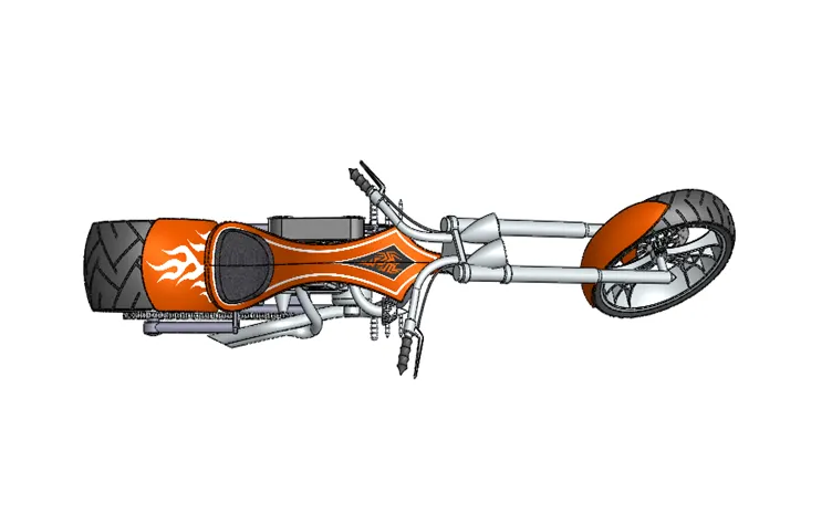
TOP VIEW
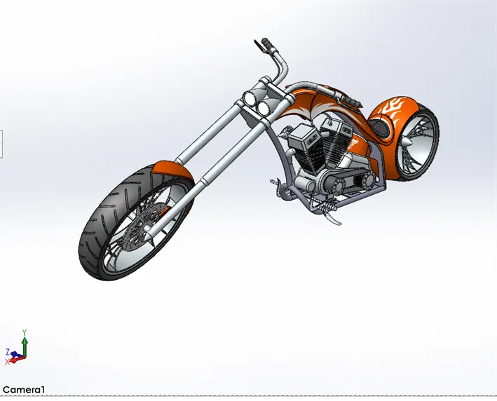
CAMERA VIEW
SETTING DECALS, SCENE, LIGHTS CAMERA SETUP:
DECALS: Decals can add a personal touch to a variety of surfaces, in our chopper we used on a gas tank, oil tank, and rear fender.
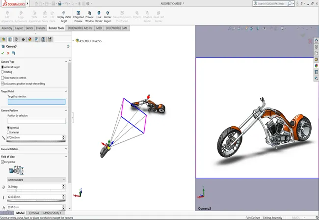
SCENE AND LIGHTS: solid works have scene and lights setups we can customize the environment of the motorcycle by applying the different scenes also we can add an HDR environment it gives reflections and shadows to the chopper. various light effects such as directional lights, spotlights, point lights, and sunlight can be used according to the applications.
CAMERA: in solid works, we can add multiple camera views. camera view setting the desired lights and the focal distance creating the angle of the view and saving the camera angle which gave a realistic view to the chopper.
RENDERING IN PHOTO VIEW 360:
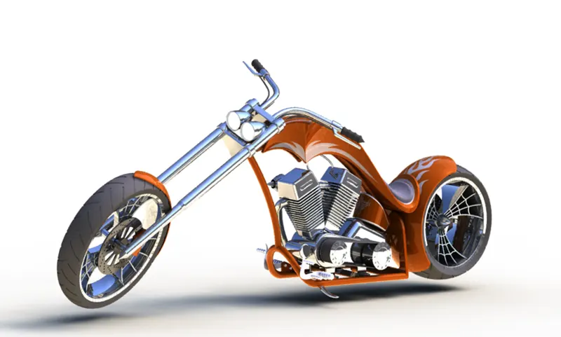
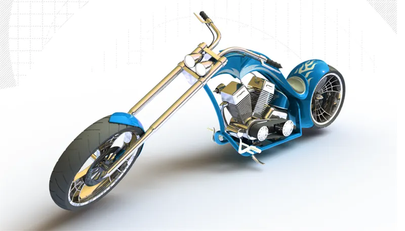
Rendering in photo view 360 produces photo-realistic renderings of models. The rendered image incorporates the appearances, lighting, scene, and decals included with the model. Photo View 360, options control output image size and render quality.
Photo view provides two ways to preview renders in the graphics area integrated preview and a separate window preview window. Both methods help to assess changes quickly before performing a full render.
You can experiment with controls that affect rendering When you are satisfied with the settings, you can perform a full render.
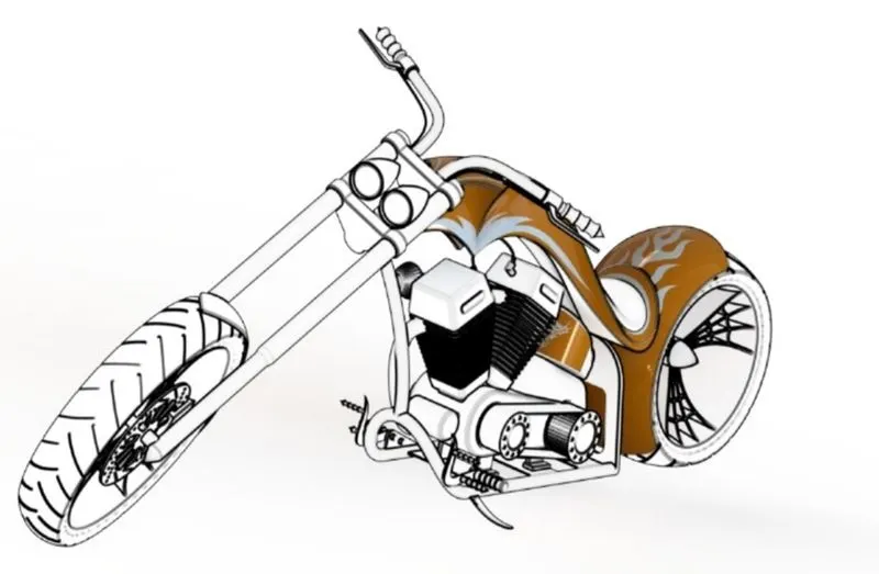
You can use cartoon rendering in photo view 360 to make the model rendering appear hand-drawn.
Advanced image processing in Photo view 360
RENDERING IN SOLIDWORKS VISUALISE:
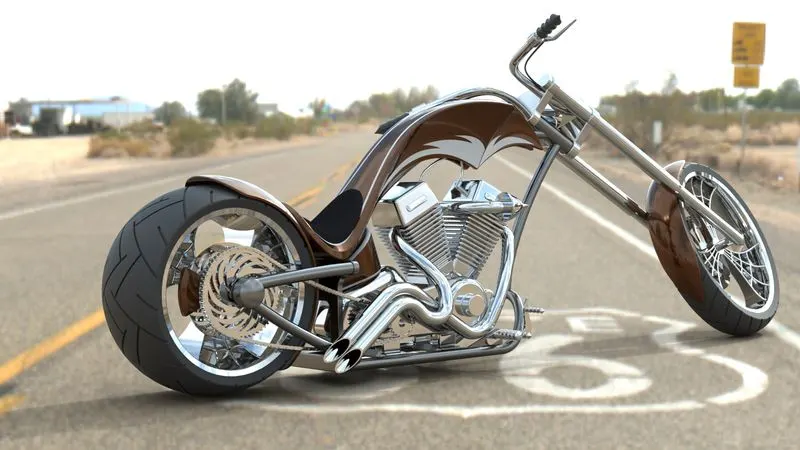
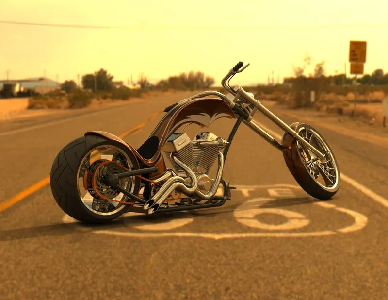
Visualize allows you to leverage your 3D CAD data to create photo-quality content in the fastest and easiest way you can–from images to animations, and immersive Virtual Reality. Through solid works visualize making the product more and more realistic with adding the background changing the and adjusting the brightness, shadow density, and gamma levels according to the different requirements of the different backgrounds changing the color of the model, and checking what suits the best with which background until we get the desired and astonishing product ready.
Conclusion:
Part modeling and assembly completed in solid works. To give realistic views and looks rendering is performed in photo view 360 and Solidworks Visualize.