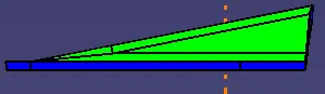
Week 8 - Challenge 2 - Base Bracket Design
OBJECTIVE:Create the Base Bracket Plastic component through the given Class-A surface. To begin with, the tooling axis for the given Class-A Surface should be created meeting the requirements of the draft angle and at the end perform the Draft analysis on the model.
DETAILED REPORT
CLASS A SURFACE: Class-A is a term used in specifically in automotive design. It describes the final production surface data for the aesthetic parts of the car.
CLASS B SURFACE: This surface is created by taking the offset fom the class A surface and it is the surface on which all the mountings and ribs are created
CLASS C SURFACE: It is the surface which joins class A and class B together
TOOLING AXIS: It is the direction in which core and cavity opens & closes
PROCEDURE:
- check the continuity of class A surface and ensure that it was propery joined without any discontinuity.this can be done by using join or boundary comand in CATIA v5
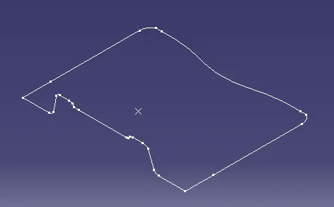
- Extracting the boundary of given class A surface and we also check continuity visually.below fig shows the continuity of class A surface
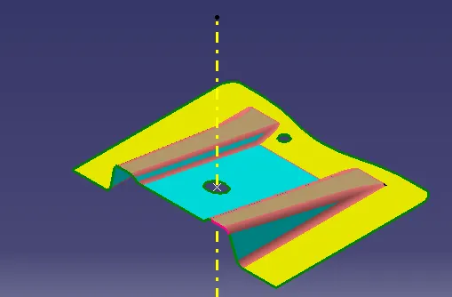
- to decide the dummy tooling axis direction by analyzing model visually to see which direction is most suitable for tooling axis
- create a plane on yz plane parallel through point and then create an intersect line on the created plane as shown in the figure
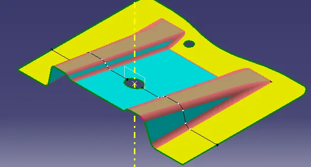
- create an extended line for the each intersect line inorder to avoid the problems of draft angle as show in the fig
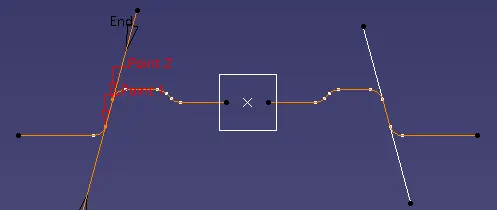
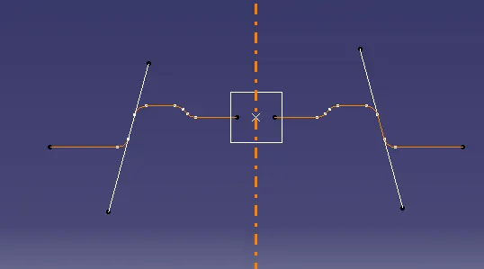
- create a Bisecting line for the extended lines and named its as tooling axis
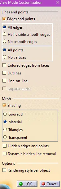
- change the view mode customization to material mode
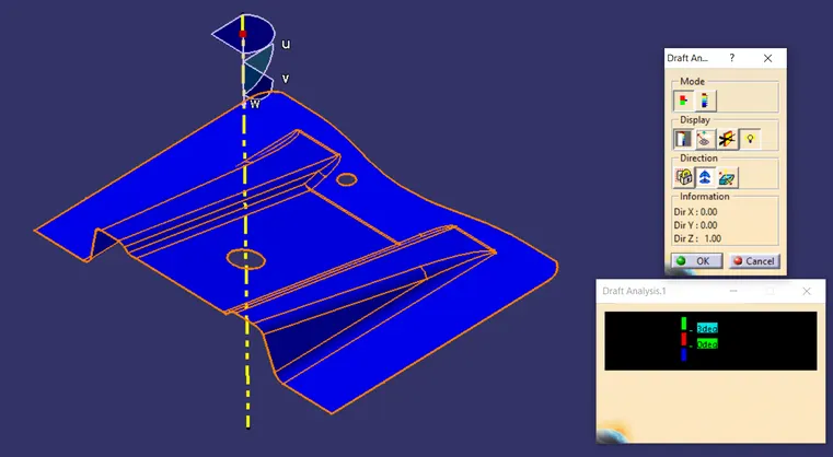
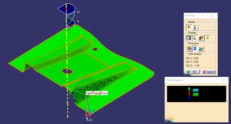
- Go to INSERT-ANALYSIS-FEATURE DRAFT ANALYSIS and move the compass towards the tooling axis and chnage the range to 3
ISOMETRIC VIEW
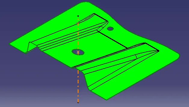
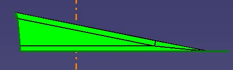
SIDE VIEW
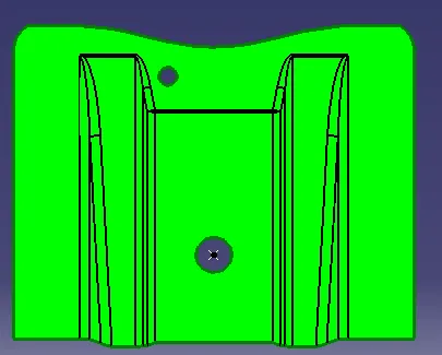
TOP VIEW
INVERSE DRAFT DIRECTION
RUNNING POINT OF DRAFT ANALYSIS
STEP2: Creating CLASS B SURFACE FROM GIVEN CLASS A SURFACE
- We divide class A surface & we work on each surface seperately to create class B surface
- we create RIB1 AND RIB2 by extract the surfaces from class A and untrim the surface-Extrapolate it-OFFSET it by 2.5mm distance as shown below
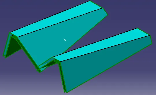
- SLANT SURFACE: extract the flat surface and offset it by 2.5mm and untrim the surface and extrapolate it by 10mm
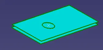
- After offsetting all the surfaces we have to trim these surfaces together to get our final CLASS B surface
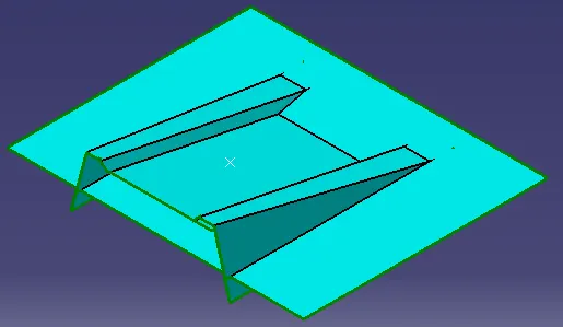
- The final trim is our inner surface so fillet the edges of the surface =class A surface fillet value +part thickness 5.5mm
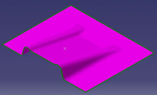
CREATING CLASS-C SURFACE TO JOIN A&B CLASS SURFACE
- Extract the boundary of the class A surface & edges of the holes
- sweeping the boundary of class A surface & edges of the holes with the use of draft direction as tooling axis
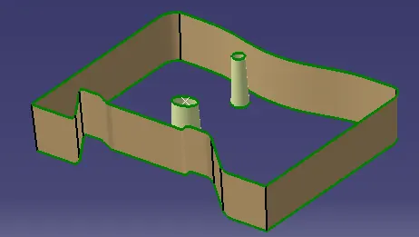
- join the class A & class C surface together
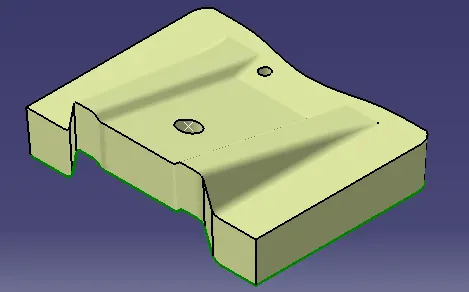
- Trim the class B surface with joined surface created earlier and after trimming we get the final base bracket close surafce
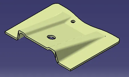
- creating solid feature by using close surface and solid odel is created from closed surface in the part work bench
ISOMETRIC VIEW
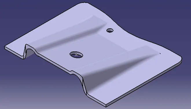
TOP VIEW
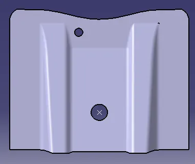
SIDE VIEW
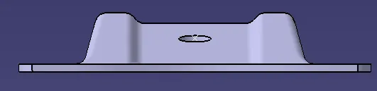
DRAFT ANALYSIS
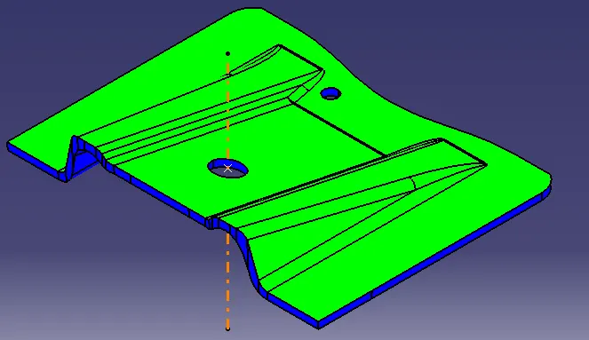
ISOMETRIC VIEW
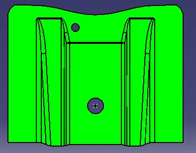
TOP VIEW
SIDE VIEW