Week 8 - Challenge 2 - Base Bracket Design
AIM:
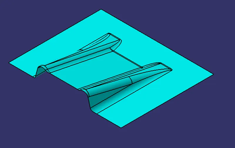
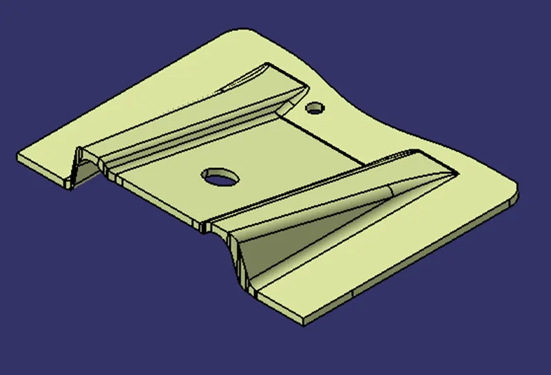
The aim of this project is to create a Class B surface and Class C surface by using the given Class A surface and perform the draft analysis.
DRAFT ANGLE IN PLASTIC:
Draft is the providing angle or tapers on product feature such as walls, ribs, posts and bosses that lie parallel to the direction of release from thmold eases part ejection.
for doing the draft analysis, a tooling direction is required.
DRAFT ANALYSIS TOOL IN PLASTICS:
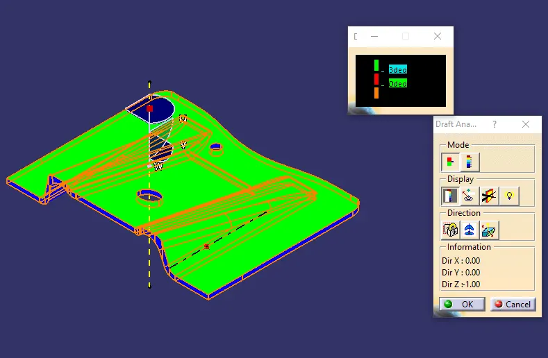
By using draft analysis tool, it identifies the zone (using colour code) and highlights the area which deviates from the specified values along a defined draft direction.
PROCEDURE FOR DRAFT ANALYSIS:
- Set the customised rendered style
- Select the draft analysis tool
- Adjust the draft direction to molding axis using compass
- Observe colour range
Green colour for draft angle less than 3 degrees
Red colour for draft angle less than 0 degrees
Blur colour for draft angle 0 to 3 degrees.
- 3 degrees is for nominal draft
- 0.5 degrees can be manufactured at ribs
- 7 degrees for textured faces
Steps involved to find draft analysis on given Class A surface of Base Bracket:
- Create a Dummy Tooling axis along z-axis. Because by observing the part model, z-axis is the best possible draft angle.
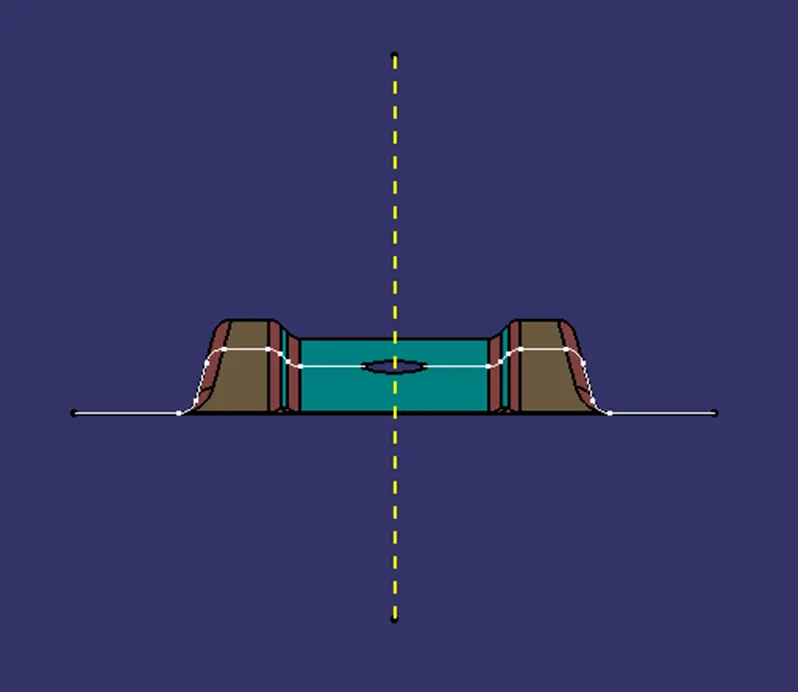
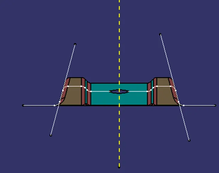
Create a Tooling direction:
Intersect the mid plane and class A surface and create two lines and bisect the another line which is represented as tooling axis.
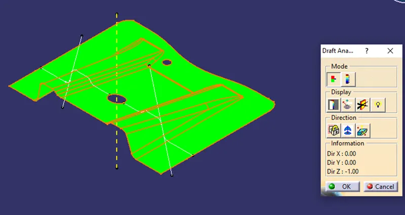
Draft analysis of given Class A surface:
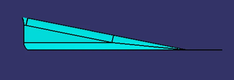
CREATION OF CLASS B SURFACE:
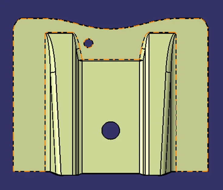
CLASS C SURFACE:
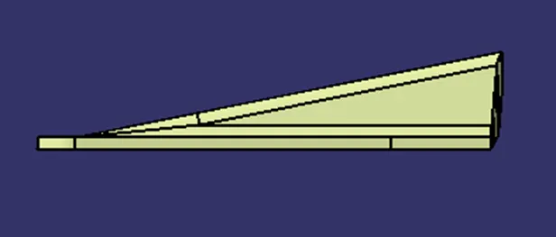
CLOSED SURFACE:
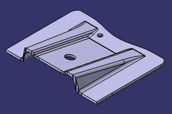
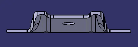
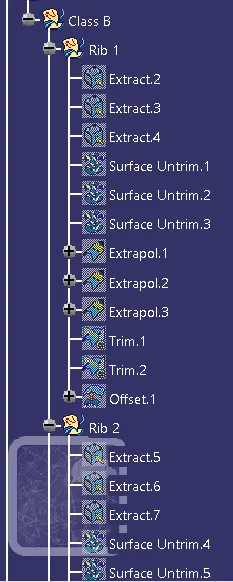
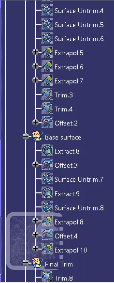
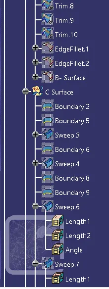
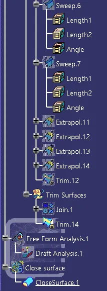
Expanded Tree:
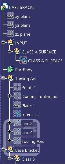
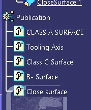
PUBLICATION:
Draft analysis on Final Component: