Week 8 - Challenge 2 - Base Bracket Design
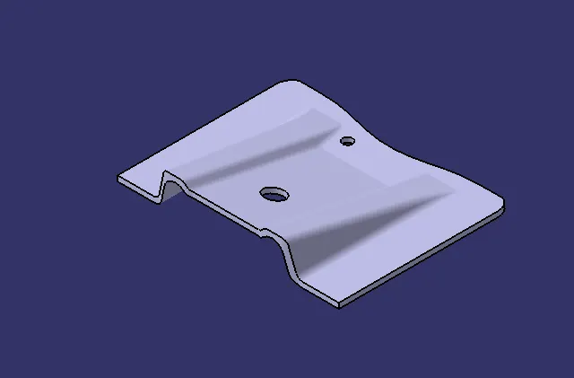
TITLE: Base Bracket Plastic Component Design Using Given Class A surface.
Objective:
To check and analyzing the draft angle of given Class A Surface and determining tooling axis.
Creating Class B, C surface to complete the base bracket model and develop solid part body with plastic design standards.
Draft analysis:
In Molding process the molded parts have to eject from the die, so there is some issues while removing the molded parts it may get sticky with the die or while removing there is chances to get damage, so that we need to setup the Draft Angle this draft angle helps the molded parts to eject from the die easily, for the plastic components the general draft angle should be minimum 3 deg. And if it is sheet metal component draft Should be 7deg. This draft is got analysed and ensuring the part is with proper draft angles.
Tooling axis Creation:
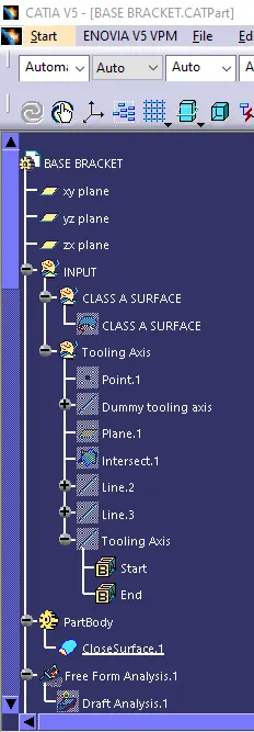
The tooling axis is basically the direction that the mold pulls apart. The mold is built in two separate pieces, Basically, it has a cavity side and a core side. The core pulls apart from the cavity along tooling direction which is tooling axis.
Steps to find the tooling axis and determining drafting analysis:
- First to ensure class a surface is properly Joined and has no discontinuity on it. For this we can use boundary command or join command.
- Analyze the model visually or manually to see which direction is most suitable for tooling direction.
- As in 3D model we can see 2 holes and flat surface, we can directly take the tooling axis perpendicular to that. But to be sure we analyze from all the views.
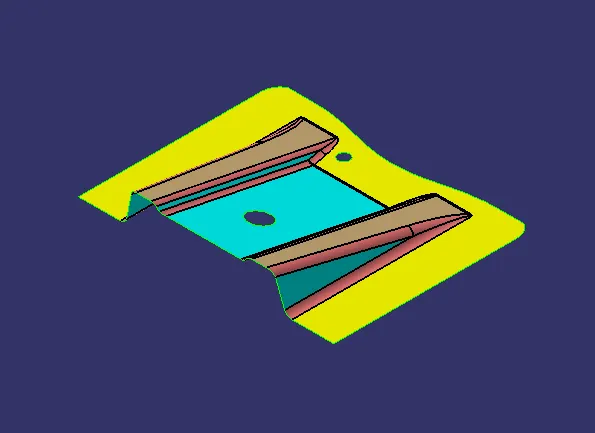
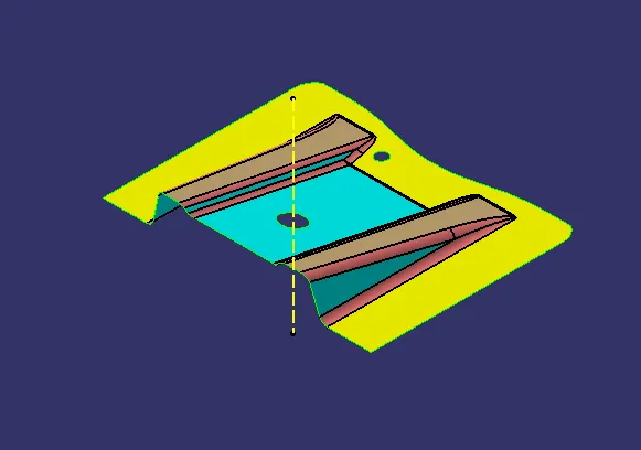
4. Create an dummy tool axis system at the center of the hole as shown fig.
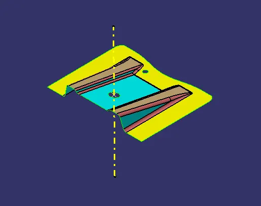
5. Create an intersecting curve (using ZX-plane and the class-A surface of Base Bracket). Create two line on draft side and derive bisecting line.
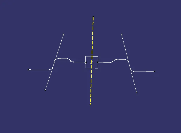
Creation of Class B:
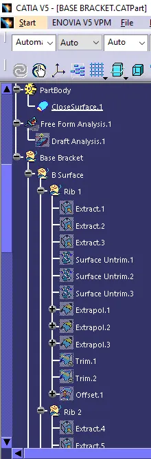
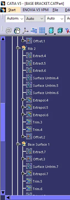
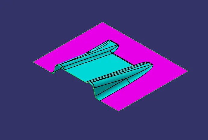
- Now for class B creation, we have extracted surface from class A and untrimmed the to obtain the original parent surface.
- These surfaces are the offset to the required thickness.
- After offsetting all the surfaces are trimmed into required shapes.
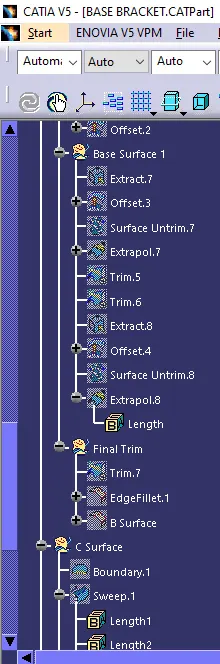
- Required fillets are given to the surface.
Creation of Class C:
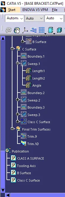
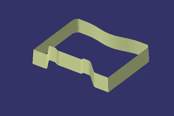
- For creating class C surface, we have created line using multi extract from class A surface and then converted to smooth curve.
- Now swept command is applied on smooth curve in draft direction and C surface has been created.
Final trims:
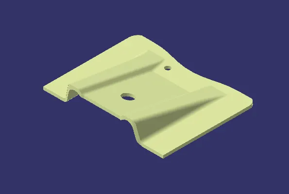
- Firstly, Class A and Cass C surface has been joined together after that this join and Class B surface is trimmed together to form single closed surface.
- Using close surface command in part workbench solid Base Bracket has been Created.
Draft Analysis:
- Go to insert <Analysis< feature draft analysis
- Click on the compass icon and align it with the tooling axis and click on the surface, we will get our result.
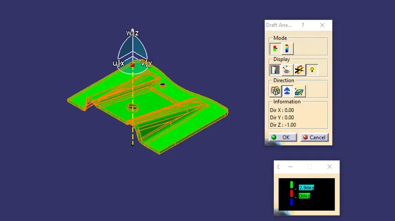
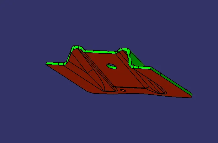
Green Color represent all surface of body meets minimum 3-degree draft angle and red face represent less than 0-degree angle of draft which act as core side in injection molding assembly.