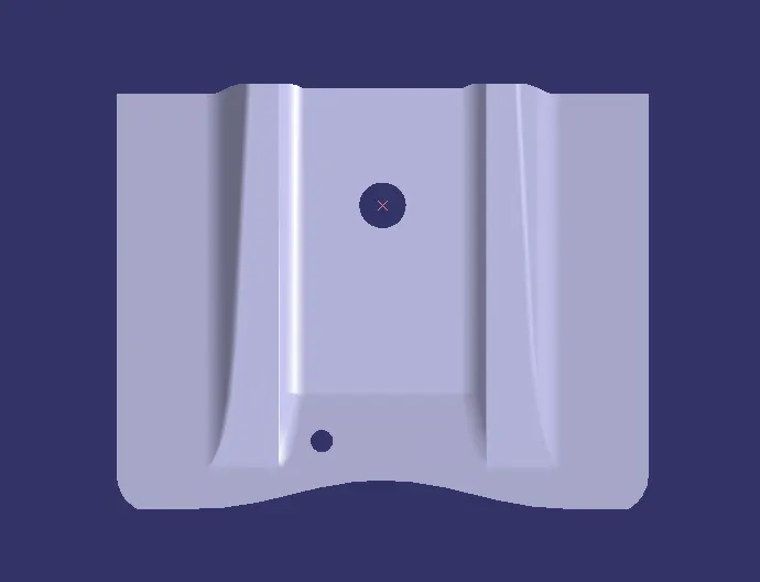
Week 8 - Challenge 2 - Base Bracket Design
BASE BRCKET DESIGN :
DRAFT ANALYSIS ON THE CLASS A SURFACE :
- Before creating the class B and class C surface we need to decide the tooling axis such that the manufacturing of the base bracket is possible and the tooling axis should be defined in such a way that the manufacturing cost of the part is minimum and avoid side cores which is an expensive process.
- First we have to define the tooling axis and perform draft analysis on the Class A surface so that wwe can find out if there is any negative draft in any of the faces we can rectify them before creating the Class B and Class C surface.
- For performing the draft analysis we need to define the Tooling Axis and such is done by the Bisecting Method.
- For fixing the Tooling direction we need to know about the core part and the cavity part. So at first we need to decide the core part and the cavity part and as per that the tooling direction is fixed.
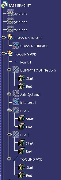
- For creating the Tooling Axis we follow the Bisecting Method approach in which first we create a dummy axis normal to the holes because the holes should be created during the plastic molding process and should be in the tooling direction so that they are not required to manufacture later and side cores can be avoided if we keep the holes in the direction of tool moving axis.
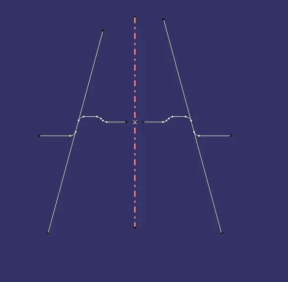
- So a dummy axis is created normal to the hole and the entire class A surface is intersected by the remaining two perpendicular planes to find out the sections and check the surfaces that are tapered and correct draft is given in that face or not which will clear the draft analysis test.
- After that lines are drawn following the taper profile and these two lines are then bisected to create another bisecting line. Same procedure is carried out for the other face and the 2 bisecting lines are then bisected agin to form our Tooling Axis.
- But in the Base bracket case we have only one tapered face which need to be checked and the bisecting line formed by using the section lines becomes our TOOLING AXIS.
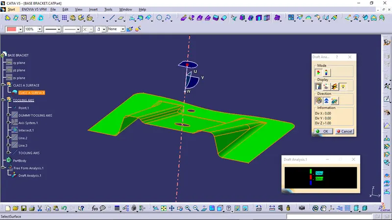
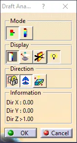
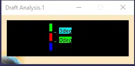
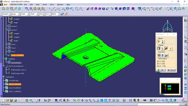
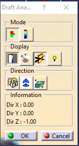
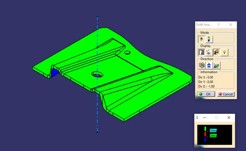
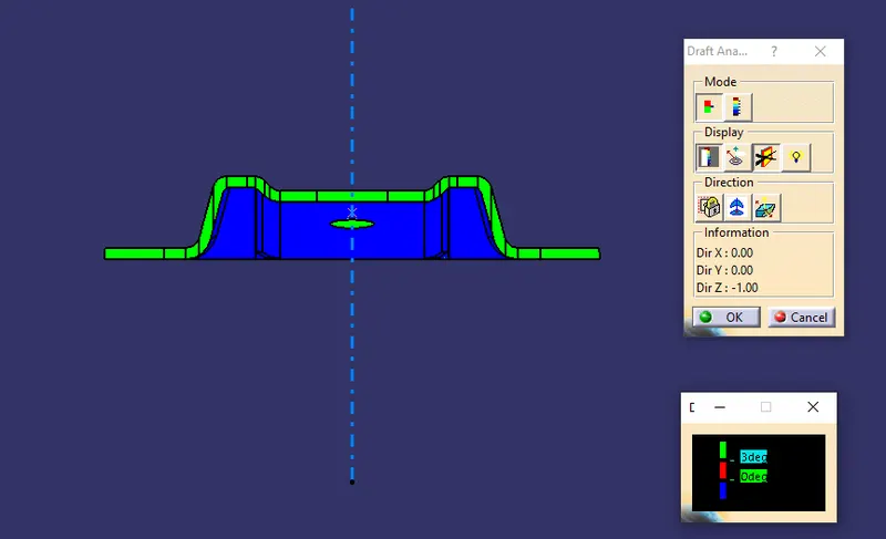
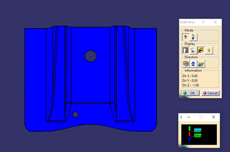
- After creation of the Tooling Axis Draft Analysis is carried on the Class A Surface to check that the minimum draft angle given on the part is 3 degree or not.
- And after creation of the Class B and Class C surface Draft Analysis is performed on the solid part or the Plastic component to check whethere proper draft angle is maintained or not so that the part or the component is manufactureable.
The report of the Draft Analysis are attached below :
CREATION OF TOOLING AXIS :
DRAFT ANALYSIS ON CLASS A SURFACE :
DRAFT ANALYSIS ON SOLID PART :

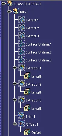
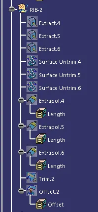
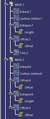
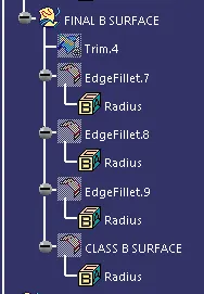
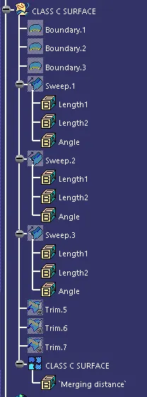
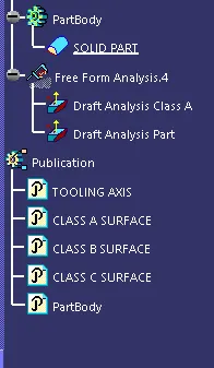
TREE STRUCTURE :
DIFFERENT VIEWS OF THE SOLID WITH DRAFT ANALYSIS :
ISOMETRIC VIEW :
FRONT VIEW :
BACK VIEW :
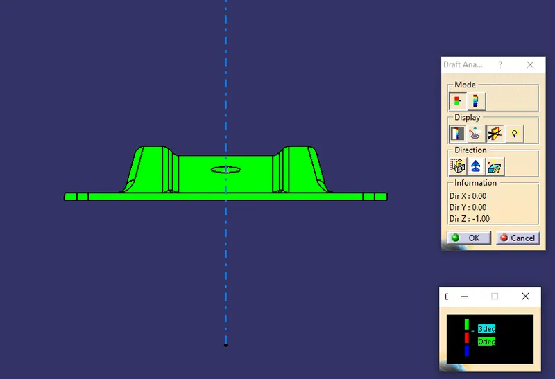
LEFT VIEW :
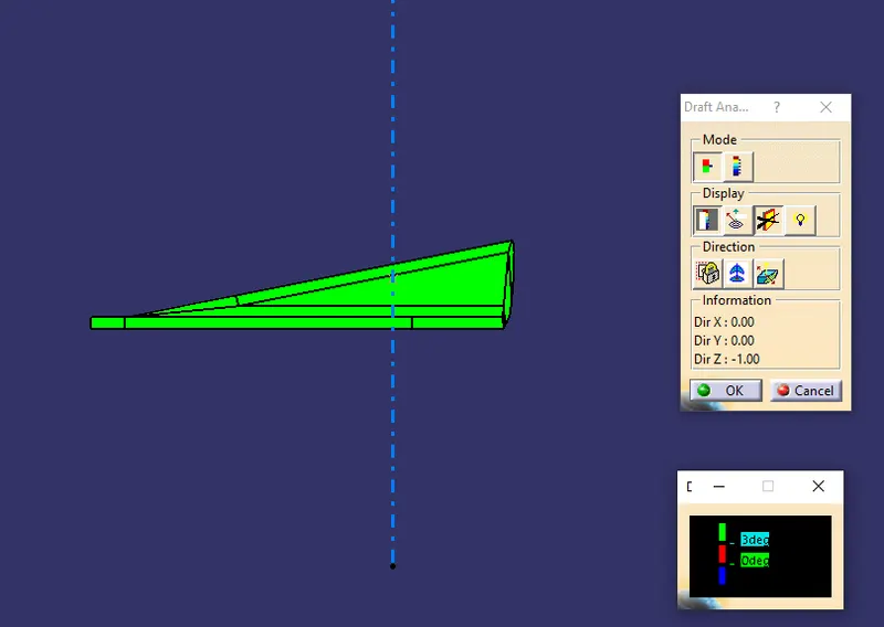
RIGHT VIEW :
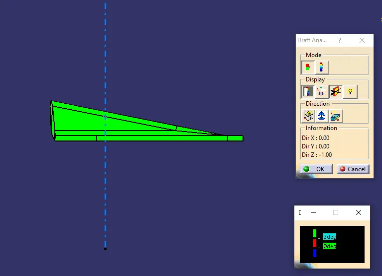
TOP VIEW :
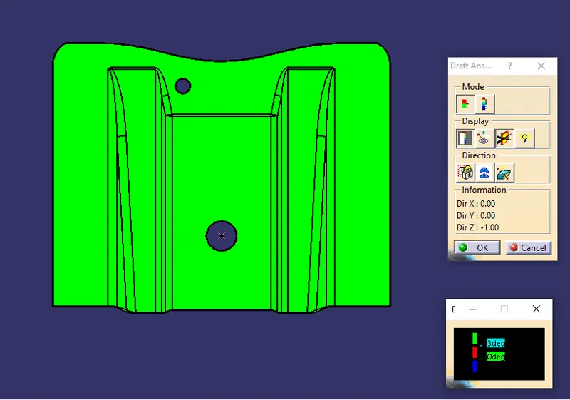
BOTTOM VIEW :
DIFFERENT VIEWS OF THE SOLID PART :
ISOMETRIC VIEW :
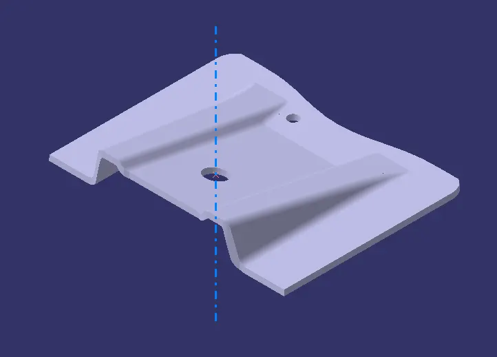
FRONT VIEW :
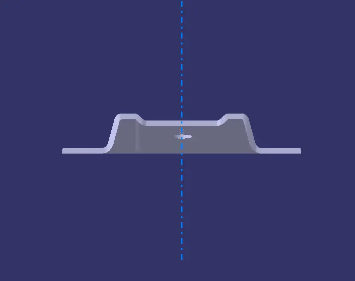
BACK VIEW :
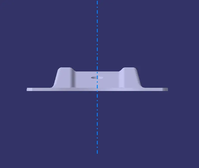
LEFT VIEW :
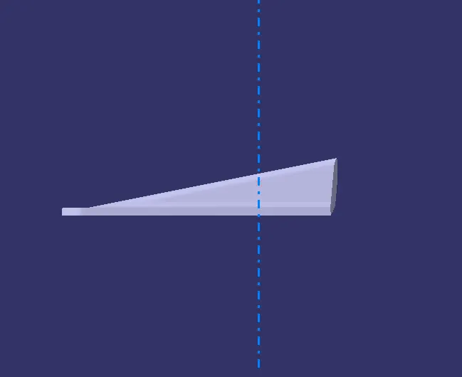
RIGHT VIEW :
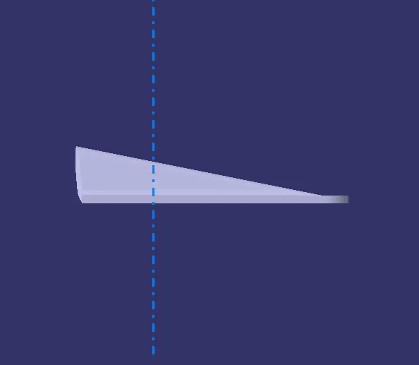
TOP VIEW :
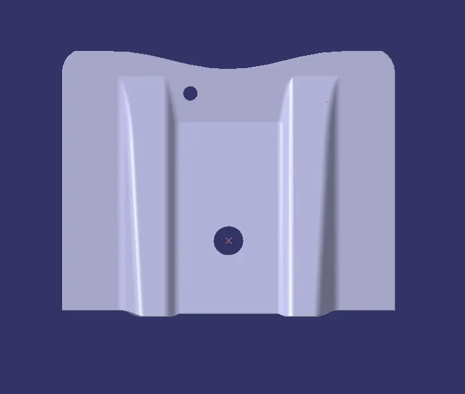
BOTTOM VIEW :