Week 8 - Challenge 2 - Base Bracket Design
Aim: Using Input Class A surface form a solid base bracket model
Objective:
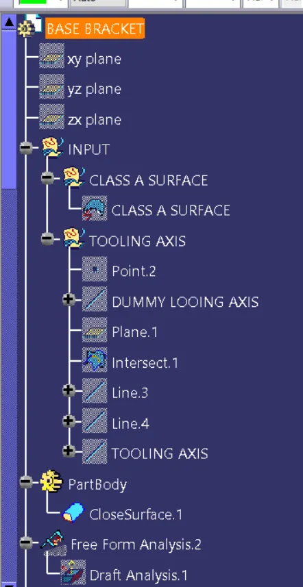
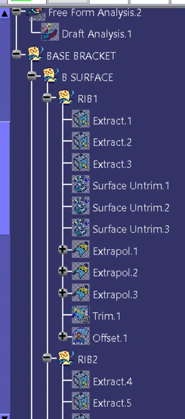
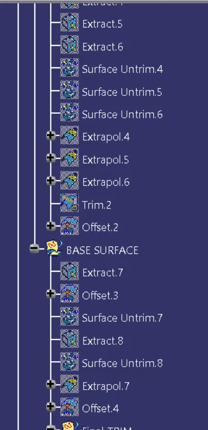
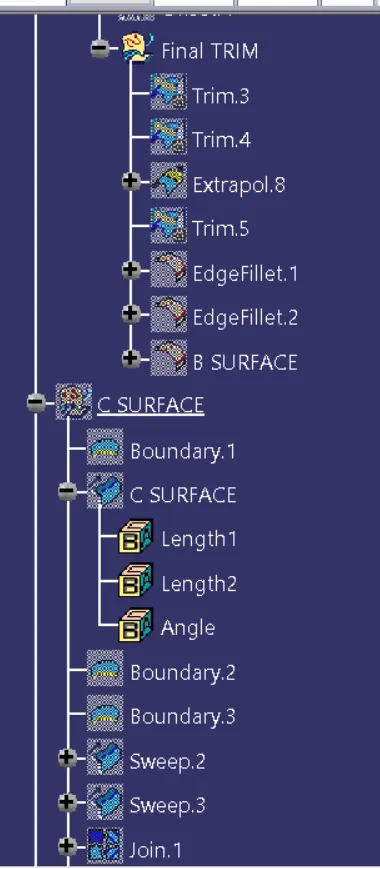
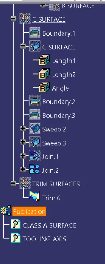
- Ensure Proper tree structure
- Ensure Proper naming of Geometrical Sets
- All sketches should be created under geometrical sets
- Creation of tooling Axis
- Draft analysis of class A surafce
- Cereation of class B and class C surface
- Creation of solid out of closed surface volume
Introduction:
Before proceeding with model we need to undertsand what are the different types of surafces used in modelling
- Class A surfaces – Represent visible surfaces of components or input surfaces. Considered are quality of connections between patches, as well as aesthetics,
aerodynamics, and passive safety related aspects. - Class B surfaces – Represent internal or functional surfaces. This cluster exemplary includes derived surfaces created by offset operations from class A surfaces
to define the thickness of material. In this file it is important to link class B surfaces geometrically to enable an adaptation to class A surfaces automatically in case of styling change. - Class C surface- This surface is used to join the surface A & surface B to give the closed volume of the surface to form solid.
Procedure:
Check The Class A surface
Class A surface is provided as input and import this in CATIA V5.
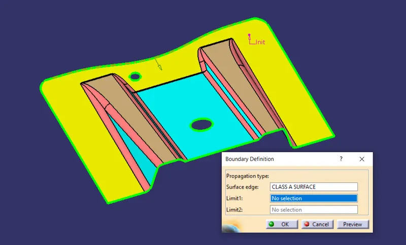
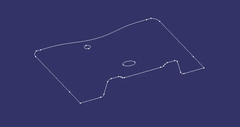
Check the connectivity of class A surface using boudary command and ensure that there is no gap between surfaces.
Tooling Axis Creation
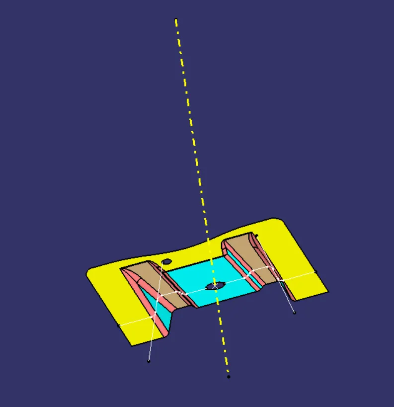
Create a Tooling Axis for the base bracket and visualise the model which axis is better for tooling axis.Create a dummy tooling axis accodring to that as shown below
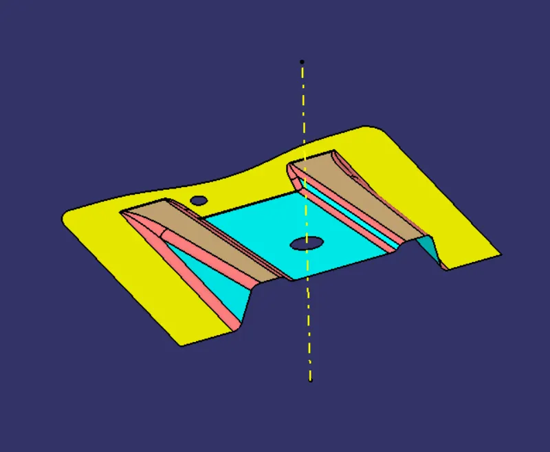
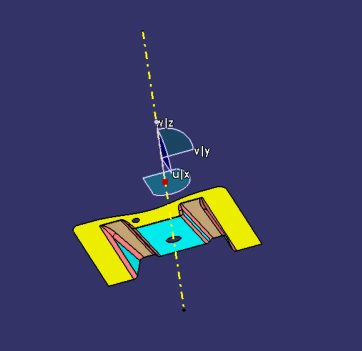
Create a point and axis system as shown below.By visualising we come to know that Z direction is correct for tooling axis.Because in X and Y direction we can not see the holes thats why we cant clear the component in this direction.
Using the intersection option select the YZ plane and Class A surface of base bracket you will get a intersection lines as shown
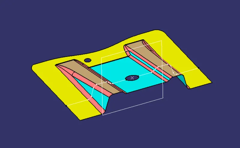
Now create a two lines with help of intersection using point to point option in line tool
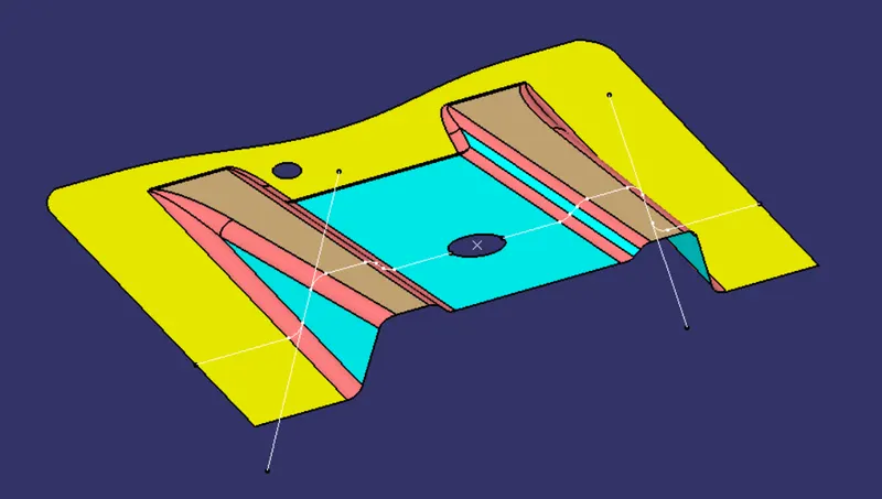
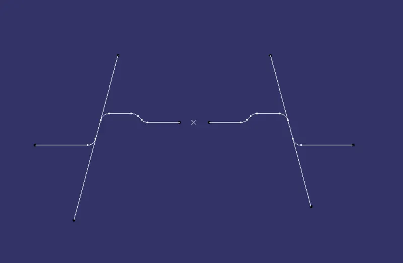
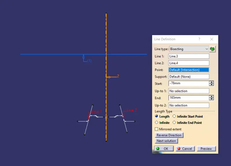
Using the line tool again bisect these two lines and you will get the final tooling axis
Draft Analysis:
Go to Insert <Anlysis
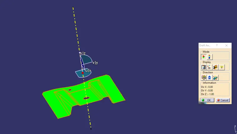
Align the tooling axis with compass
Click the surface and perform draft analysis
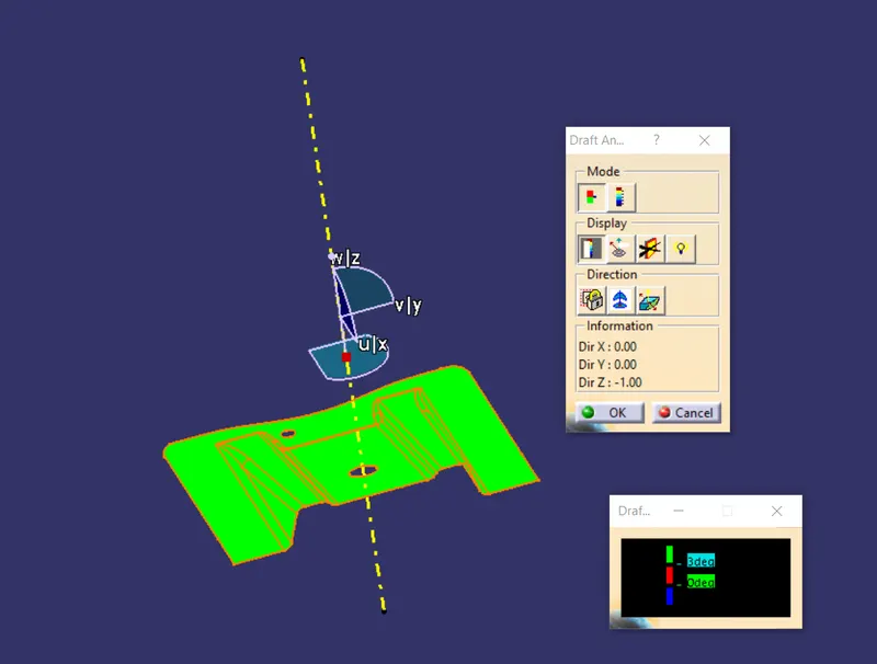
3 degree is the minimum draft given
Creation of class B surface
Extract the surface from the class A and work upon each surface one by one
Flat surface
1.Extract the Flat surface
2.Untrim the surface
3.Extrapolate Surface
4.Offset it by 2.5mm
Similarly for the Slant surface and ribs follow the same steps and trim the unnecessary surfaces to get the B surface and fillet it accorrding to class A surface
Red highlighted surfaces are extracted surfaces
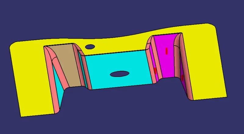
Untrim the surface
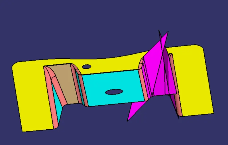
Extrapolate the surface
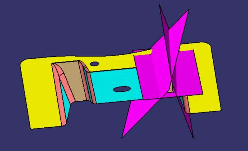
Trim the surface
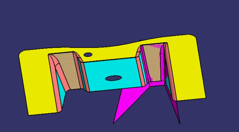
Offset it 2.5mm
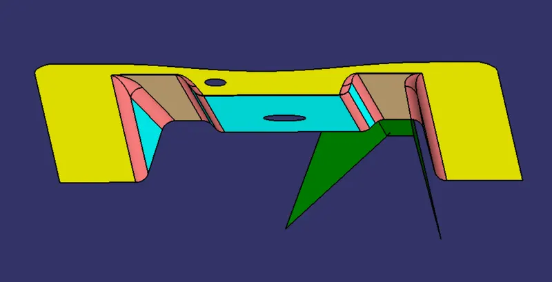
Similarly create other rib
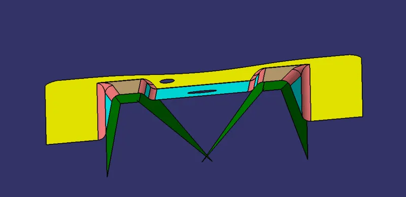
Work on slant surface
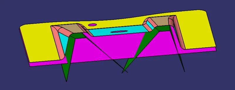
Trim the unnecessary surfaces
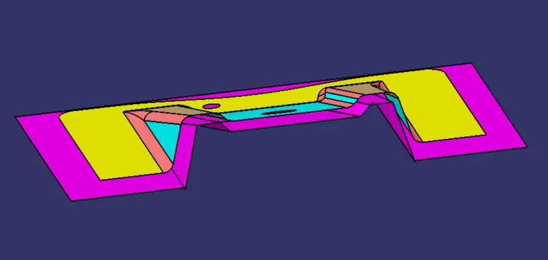
Fillet it
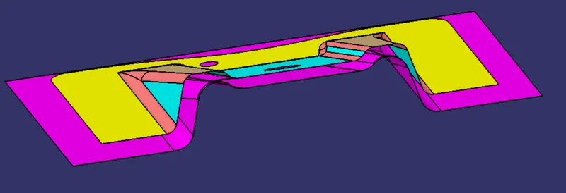
Creation of class C surface
Extarct the Boudary of class A surface and sweep it
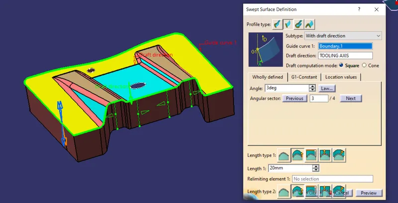
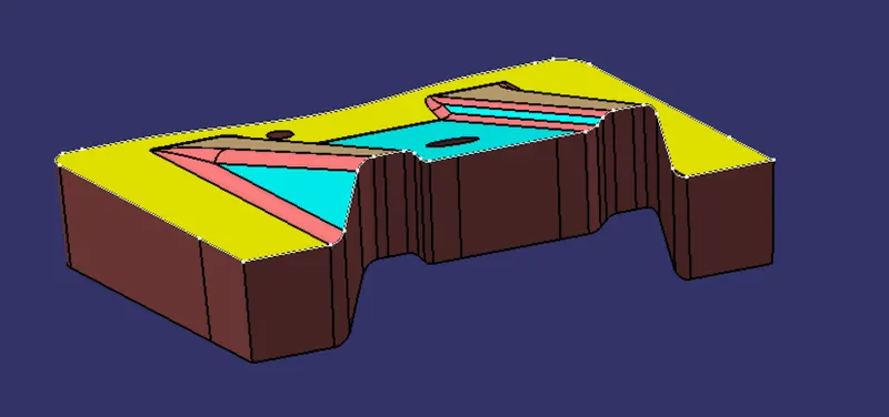
Extract the boudary of holes
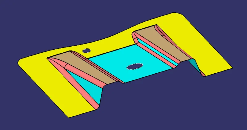
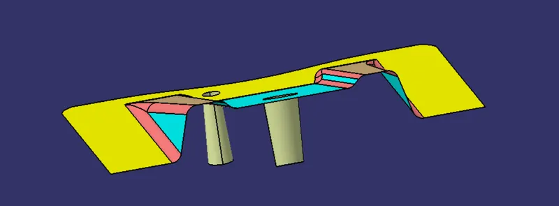
Use the sweep tool to get the desired shape of class C where it joins class A and class B surfaces
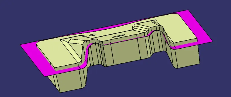
To get the base bracket trim it accordingly
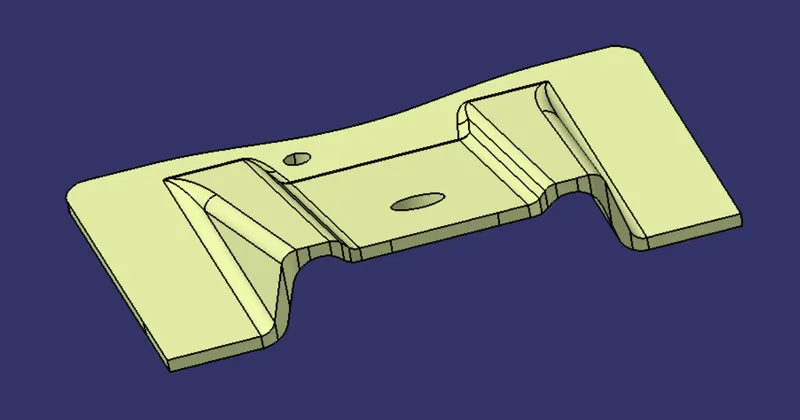
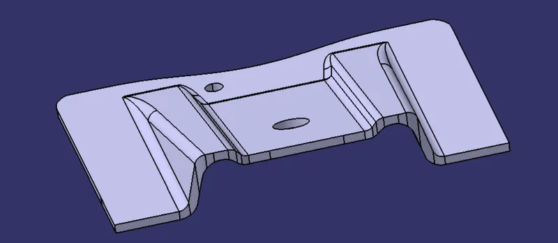
Go to part workbench and use closed volume method to get solid body.
Feature Tree
Conclusion
Automotive base bracket is created using class A surface as input using catia V5