Photo Realistic Rendering
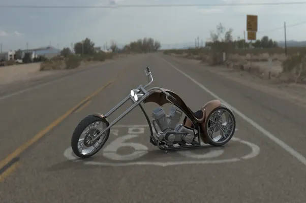
Design Of American Chopper And Photorealistic Rendering
Prepared By
Sharan Adiveppa Kubyal
Introduction
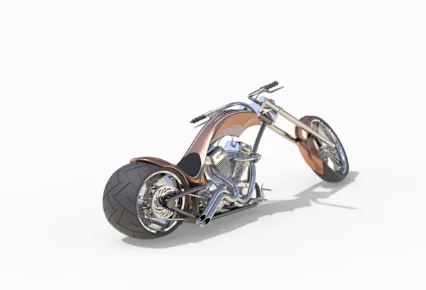
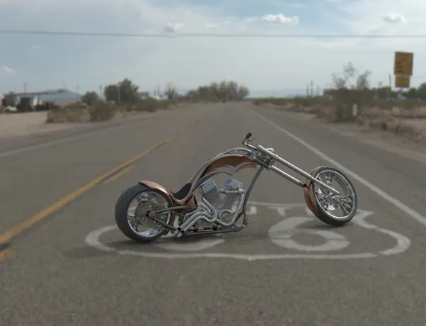
The modelling of American Chopper using Solid works software is basically to understand the design process and features used to design the different models in solid works. The complete Assembly of American chopper and its parts modelling. The Photorealistic rendering is done using photo view 360 and solid works visualise.
Objective
The main objective of this project is to understand the complete solid works software.
- Design of Individual parts using Solid Works
- Assembly of Chopper
- Adding Decals, Scenes, lights and camera
- Rendering of American Chopper using Photo View 360 and Solid Works Visualize
Part Modelling
The American chopper is made up of following parts
- Transmission Belt
- Kick Stand
- Chain
- Rear Fender
- Rear Wheel
- Pedal
- Front Fender
- Front Wheel
- Oil Tank
- Front Fork
- Chassis
- Engine
- Fuel Tank
1.Transmission Belt:
Transmission belt is used to transmit the power from engine to gear box.
Feature:
- Extrude Boss
- Fillet
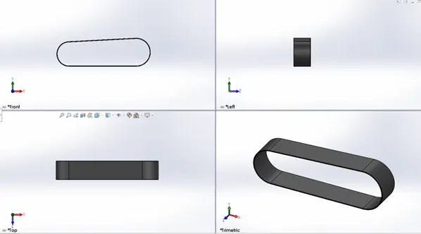
The profile of the transmission belt is created as per the dimensions in the front plane, and give the thickness of 3.5mm and exit the sketch and extrude as per dimensions and give the fillet to the square edges. Add the appearance to it matte rubber.
2.Kick Stand
Kick Stand is structure used to support the vehicle also known as side stand
Features:
- Lofted Boss/Base
- Dome
- Cut Extrude
- Split
- Boss Extrude
- Fillets
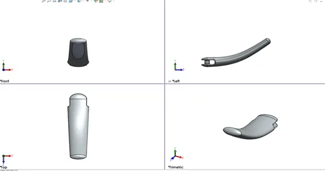
The main feature is used to create kick stand is loft. Two ellipses are created in right plane one at the top and another one at bottom. A path is created in the front plane and it should be coincident with the centre of two ellipses. Now perform the loft operation body of kick stand created. Elliptical dome feature is used to create a round edge at the ellipse. Cut the slot at the top end and create a extrude boss to hold the chassis. Finally add the appearance of chrome plate.
3.Chain
Chain is a connection used to transmit the power from engine to rear wheel.It passes through sprockets.
Features:
- Extrude boss Base
- Linear pattern
- Circular pattern
- Fillet
- Mirror
- Combine
- Blocks
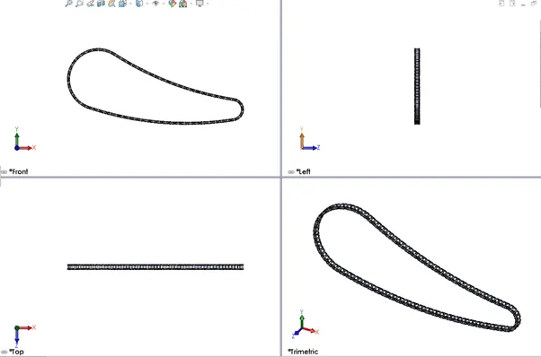
A main profile of chain is created using a three-point arc and tangent relation between arc using the dimensions. Create two sketches which are used to create inside and outside links of chain. The plates of chain links are extruded and connecting pins to be created using the same sketch. Using the sketch blocks we have to pattern it linear and circular pattern features. Then perform the mirror feature for other side of the links. Use the combine feature to make it one chain. And finally apply the chrome steel appearance.
4.Rear Fender
It is a semi cover for the rear wheel. The primary purpose is to prevent sand, mud rocks, liquids and other road spray from being thrown into the air by rotating Wheel.
Features:
- Revolve boss base
- Fillet
- Shell
- Split
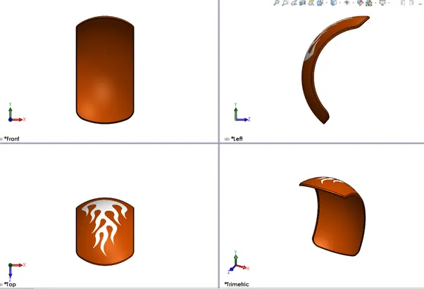
A sketch is created in the front plane using a three-point arc and offset it to meet the thickness of fender create axis at the origin and revolve it using that axis. Apply the fillets and appearance.
5.Rear Wheel
A wheel is circular block of hard and durable material where the centre has been bored with circular hole through an axle bearing about which the wheel rotates.
Features:
- Extrude boss base
- Revolve boss base
- Cut extrude
- Revolve Cut
- Circular pattern
- Fillet
- Chamfer
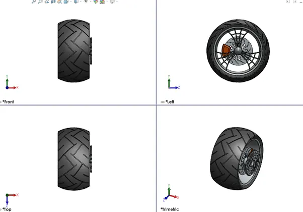
The rim is created in the sketching in the front plane and use the revolve extrude command to revolve it using imaginary axis at origin. To create a spider web sketch using the front plane and extrude it as per the dimensions. For Rotor sketch on the front plane and extrude it to required dimensions create holes using circular pattern. For caliper create a sketch using lineand circle and remove unwanted things and extrude the caliper profile and give fillets and chamfer. Create sprocket and tyre give the separate appearance to each parts.
6.Pedal
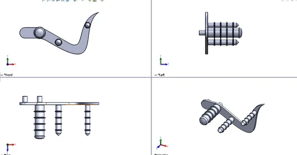
It is the part of motorcycle where the foot of rider rests and it gives the comforts to the rider. The rider can apply gears and rear brake very easily by the support of pedal.
Features:
- Extrude
- Fillet
- Linear pattern
- Dome
- Chamfer
- Appearance
7.Front Fender
It is a semi cover for the front wheel. The primary purpose is to prevent sand, mud rocks, liquids and other road spray from being thrown into the air by rotating Wheel.
Features:
- Revolve boss base
- Fillet
- Shell
- Split
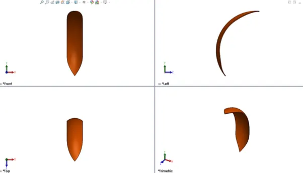
A sketch is created in the front plane using a three-point arc and offset it to meet the thickness of fender create axis at the origin and revolve it using that axis. Apply the fillets and appearance.
8.Front Wheel
A wheel is circular block of hard and durable material where the centre has been bored with circular hole through an axle bearing about which the wheel rotates.
Features:
- Extrude boss base
- Revolve boss base
- Cut extrude
- Revolve Cut
- Circular pattern
- Fillet
- Chamfer
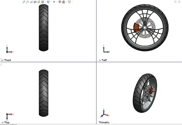
The rim is created in the sketching in the front plane and use the revolve extrude command to revolve it using imaginary axis at origin. To create a spider web sketch using the front plane and extrude it as per the dimensions. For Rotor sketch on the front plane and extrude it to required dimensions create holes using circular pattern. For caliper create a sketch using lineand circle and remove unwanted things and extrude the caliper profile and give fillets and chamfer. Create sprocket and tyre give the separate appearance to each parts.
9.Oil Tank
The main purpose of oil tank is to store the oil and lubrication to the parts to avoid wear and tear.
Features:
- Extrude boss
- Fillet
- Shell
- Combine
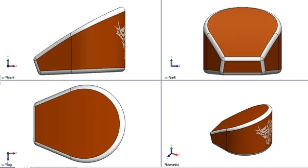
On the top plane create sketch by a 3-point arc and few lines apply tangent relations. Then extrude the profile and obtain the structure and front plane create one more structure combine them both to get proper shape of tank. Give the proper thickness using shell command. Apply the appearance to it.
10.Front Fork
Front fork is used to guide the vehicle and it supports front wheel and provides suspension to the vehicle. The most commonly used suspension systems used is hydraulic shock absorbers.
Features:
- Extrude boss base
- Revolve boss base
- Extrude cut
- Revolve cut
- Projected curve
- Swept boss base
- Dome
- Combine
- Mirror
- Chamfer and fillet
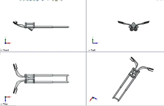
Create sketch on front plane with proper dimension and exit the sketch and revolve it the tube is created. Create the half of the triple clamp and create the head light by revolving command. To create handle using revolve command and cables are using projected curves and apply the appearance as required.
11.Chassis
It is the supporting structure for the vehicle where it holds engine and rear wheel ,pedal, front fork etc.
Features:
- Extrude boss base
- Revolve boss base
- Extrude cut
- Revolve cut
- Linear pattern
- Projected curve
- Swept boss base
- Dome
- Combine
- Mirror
- Chamfer and fillet
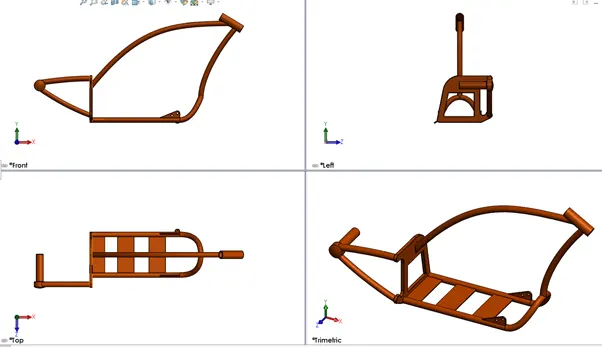
The blue print of motor cycle is imported and create the sketch as per the blue print and use splines and projected curves to create the structure. Apply the appearance at the end.
12.Engine
Engine is the most important part in the vehicle where the power is generated and transmitted to the rare wheel. Using the fuel it generates the power and gives required motion to the vehicle.
Feature:
- Extrude boss base
- Revolve boss base
- Extrude cut
- Circular pattern
- Projected curve
- Swept boss base
- Dome
- Combine
- Mirror
- Chamfer and fillet
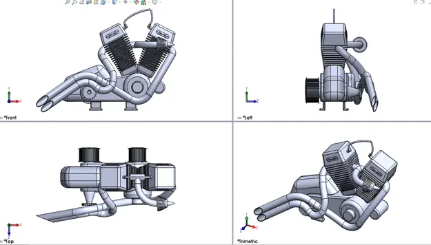
The creation of this component starts with the inserting blue print and first create the base of engine and create V shape of the engine. Create the two pulleys using the revolve command. Using the projected curve create the exhaust pipes and spark plug created at last. Apply the proper appearance to it.
13.Fuel Tank /Gas Tank
Fuel tank is used to store the fuel. It supplies the required fuel to engine.
Features:
- Surface Loft
- Surface Knit
- Projected Curve
- Fillet
- Swept Surface
- Split
- Mirror
- Swept Cut
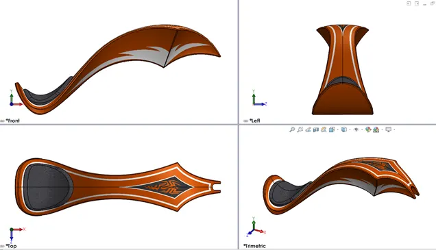
This part is created using surface tools and finally given the required thickness. Apply the appearance to the part.
Assembly of Chopper
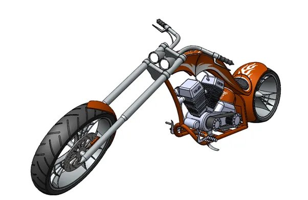
All the components are inserted into the assembly section and provide the required mates to each part. Ensure that the parts should be fully defined and properly assembled without any crash with other parts if there modify the parts.
Rendering of American Chopper
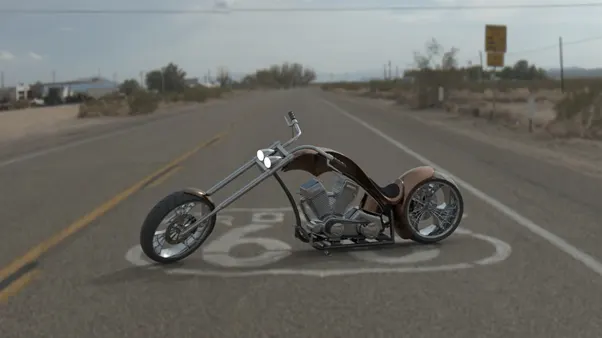
Rendering is done using Solid works visualize or Photo view 360.Redering follows the following steps
- Adding decals to the components
- Setting up the scenes, lights and camera
- Render using Solid works Visualize
Conclusion
- The components of American Chopper modelled in Solid Works
- The parts are inserted in Assembly environment and apply the mates
- The rendering done using Solid works visualize