Advanced Sheet Metal Design Using NX Cad Challenge_1_Casing Design
Advanced Sheet metal Design Using NX cad Challenge 1 Casing Design:
Sheet Metal Design of Casing
Objective:
The objective of the project is to design sheet metal casing using siemens NX Cad software.
Introduction
Sheet metal is metal formed by an industrial process into thin, flat pieces. Sheet metal is one of the fundamental forms used in sheet metal work and it can be cut and bent into a variety of shapes. Countless everyday objects are fabricated from sheet metal. In this project we are designing casing box used in assembly of casing.
Design Methodology:
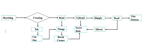
Features used
Tab: Tab is basically used for creating a base, it is main feature to create any sheet metal parts, it gives thickness to the material.
Normal Cut out: Cuts the material according to profile created and also perpendicular to faces of sheet metal.
Bend: Bend modifies the sheet metal parts by bending it according to profile.
Flange: Adding flange gives sheet metal by selecting edge of base of the model, it gives flange to the base of the model in an angle and desired length.
Break Corner: In this feature the sharp edges will be modified to round or chamfer.
Unbend: Flattens the bended area.
Mirror: The features or entity can be copied to other side by using mirror feature by selecting the required plane or centre line.
Hole: Hole is created by using this feature.
Dimple: Lifts the area of model inside the profile created and it is like stamping tool.
Bead: Lifts the material along the contour of a sketch that simulate stamping tool.
ReBend: It is used to restore the unbend feature to bend feature.
Flat Pattern: Creates the flat pattern from the formed sheet metal part.
Procedure for Designing:
- Create a sketch on XY plane using the rectangle and finish the sketch and give tab to it, the base is created
- Use normal cut out feature to create a cut out of sheet metal part creating rectangle in XY plane
- Draw two parallel lines on XY plane and bend the sheet metal part
- Use Break corner to fillet the sharp edges
- Unbend the faces keeping the large face as stationary face
- Sketching four points on flanges and create screw clarence hole using a hole feature
- Dimple is created using studio spline at the centre of XY plane by selecting the pole option
- The bead is created by circle profile using XY plane
- Features are mirrored as required
- Rebend the sheet metal part in the final.
Different Views of Casing:
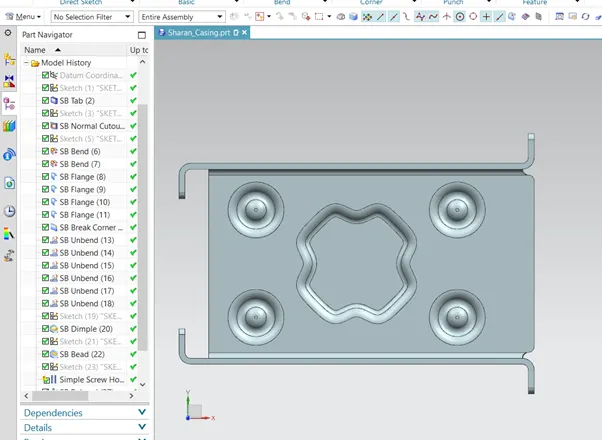
Front View
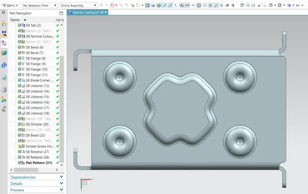
Top View
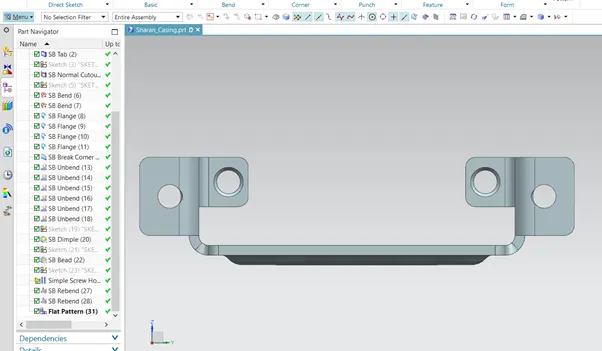
Side View
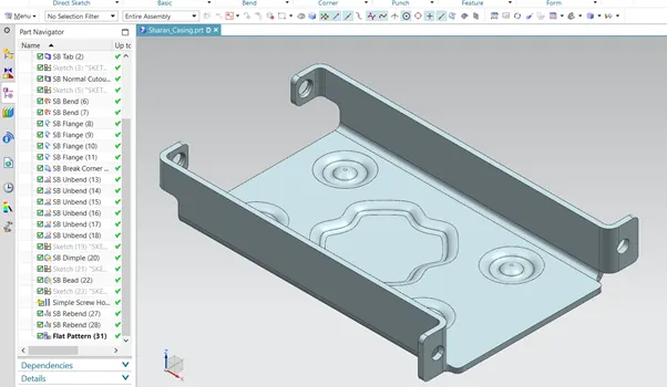
Isometric View
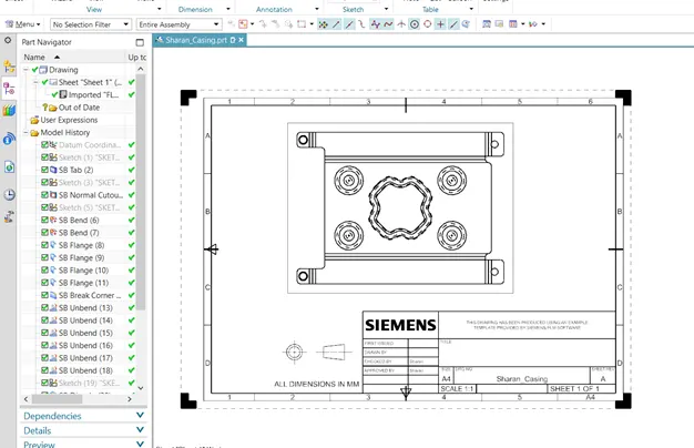
Drawing Sheet:
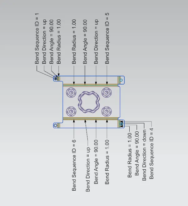
Flat Pattern View
Conclusion:
The casing is created by appling design methodology using NX Cad