Radar Mast & Final Assembly of Yacht
SUNSEEKER PREDATOR YACHT
DESIGN AND ASSEMBLY IN SOLID WORKS WITH PHOTO REALESTIC RENDERING
Objective
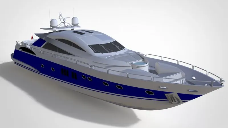
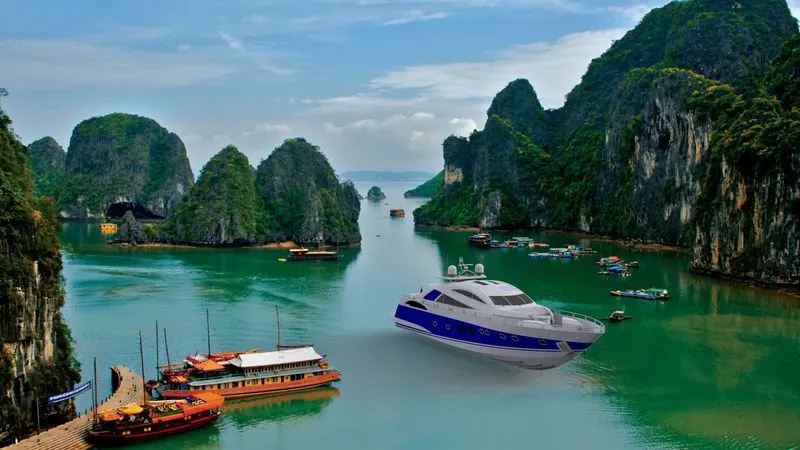
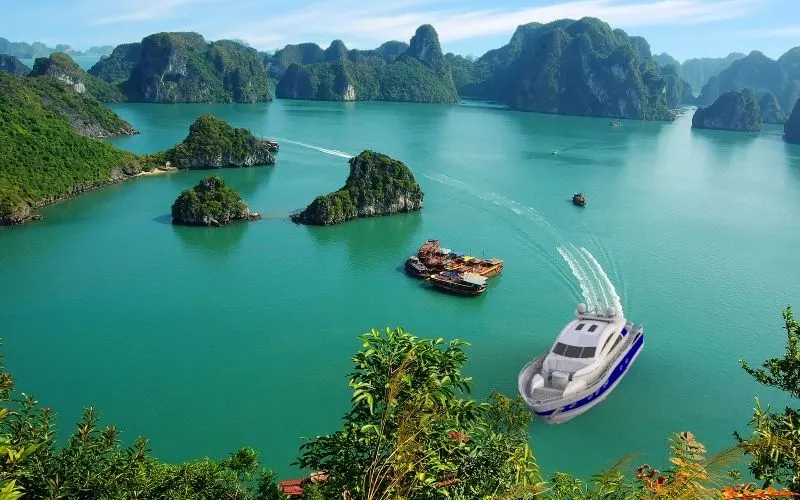
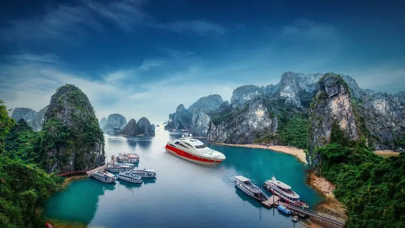
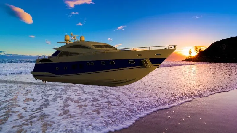
The objective of this project is to design and model all parts of a sunseeker predator yacht and assembling it to create the photo realistic rendering
Introduction:
Back in 1969, in the English seaside town of Poole, Robert Braithwaite dreamt of building a new kind of boat. Using revolutionary materials and technology, his early designs were tailored to a handful of customers, keen to embrace newfound freedoms. When Robert sailed his first little cruiser in 1971, it wasn’t just a boat he launched. It was an entirely new world of boat making. Throughout the decades, Sunseeker has always pursued the more advanced, the more ambitious, the more creative – and consequently, the more successful. Today, Sunseeker International employs a dedicated team of over 2,200 highly skilled designers, engineers and master craftsmen supported by a worldwide network of over 120 retail and service locations, exporting c.150 yachts a year to more than 74 countries. Sunseeker has always stayed true to this thought. With their passion to seek perfection and exceed boundaries stronger than ever. The brand’s enormous global strength can be greatly attributed to its commitment to constantly set new standards and exceed what came before. Breaking new waves. Discovering new horizons.
Design methodology
Features and command used in modelling of Yacht
Sketch: create the sketch in different planes using this command.
Line: It is used to draw vertical, horizontal and inclined line
Circle: circular feature is created using this command
Rectangle: we can create different types of rectangle according to requirements.
Spline: With the help of spline, we can create curves using spline handles
Tangent arc: Tangent arc is created by selecting two entities
Ellipse: ellipse is helpful when we require slot
Sketch fillet: Within sketch we can give fillet between two entities.
Offset entities: we can move or copy the entities at desired distance.
Smart dimension: The dimension can be given quickly and easily
Sketch Picture: this is helpful to insert an image or to create blueprint of the model
Mirror entities: Mirror the entities by creating centreline or axis
Linear sketch pattern: Pattern the sketch entities by vertical, horizontal or inclined
Circular sketch pattern: Creating pattern in circular manner with equal spacing and instances.
Convert entities: Project the entities in desired sketch plane by already created feature.
Extrude Boss/base: This feature is used to give the thickness to the 2d sketch
Extrude cut: This feature is used to remove the material according to the base sketch
Revolved Boss/Base: Material can be added or removed by this with respect to centre line or axis
Fillets: Fillet is created whenever there are sharp edges exists it will create the round in that area.
Chamfer: Chamfer is created in an angle using edge.
Combine: It is used o create multibody into single body
Sweeps: using a path and profile we can create the part
Lofts: A series of profile is used to create the loft and also guide curve is used to give the proper shape.
Projected Curve: We use to sketch to create the single curve.
Composite Curve: Here we use two curves to create the single curve.
Split line: It is helpful when we have to separate the single surface into two.
Extrude Surface: Extrude sketch to create the surface.
Lofted surface: create two or more sketch and create a loft of that sketched surface
Revolved Surface: Revolves the sketch with reference to centre line or axis.
Swept surface: it creates surface using path and profile.
Filled surface: This feature helps to create patch of the surface by selecting the edges.
Ruled surface selecting the edges we can ruled the surface in the required direction.
Trim Surfaces: in this feature we can trim the unnecessary surfaces by selecting the intersection of surfaces
Knit surfaces: It creates a two or more surfaces into one surface. It will help to create solid body.
Offset surface: By selecting required surfaces we can move desired direction of surface with specified distance.
Extend Surface: By selecting the edges we can extend the surface at a required distance.
Part Modelling
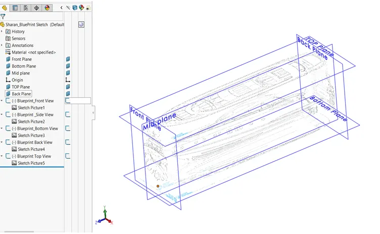
BLUEPRINT
It is the base for modelling of some of the parts in yacht design and different views of drawing is inserted in front, top, side, bottom etc to guide the model creation easier.
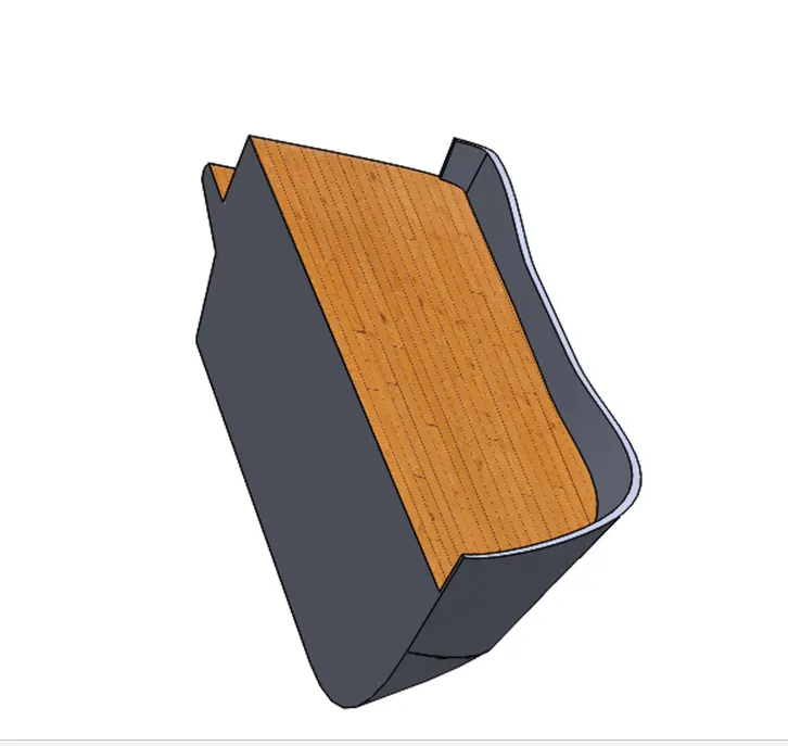
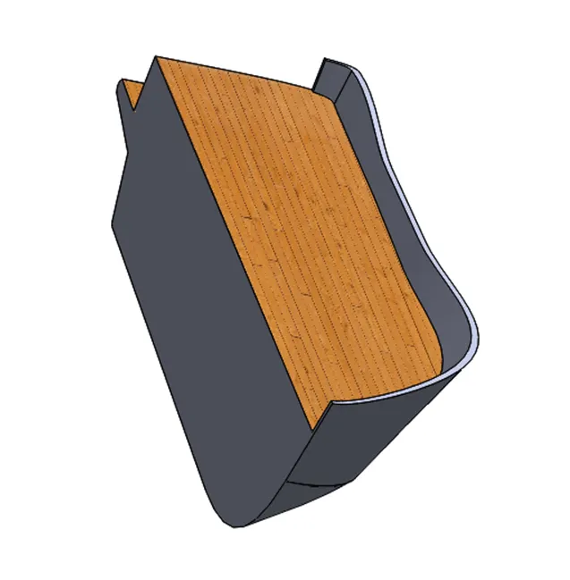
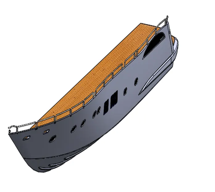
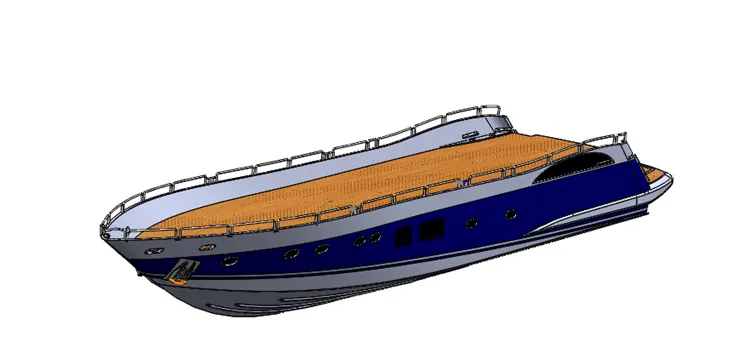
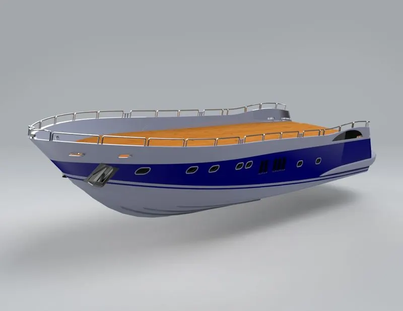
Hull
A hull is the water weight body of a ship. The hull may open at the top, or it may be fully or partially covered with a deck. Atop the deck may be a deck house and other superstructure, such as a funnel, derrick, or mast. The line where the hull meets the water surface is called the waterline.
Rendered Image:
Features Used:
- Sketch
- Projected Curve
- Lofted surface
- Surface trim
- Extrude surface
- Surface Knit
- Surface fill
- Shell
- Extrude Boss
- Extrude Cut
- Fillet
- Chamfer
- Reference plane
- 3D Sketch
- Swept Boss
- Revolved Boss
- Dome
- Helix/Spiral
- Linear pattern
- Delete face
- Mirror
- Combine
- Split
- Offset surface
- Thin Extrude
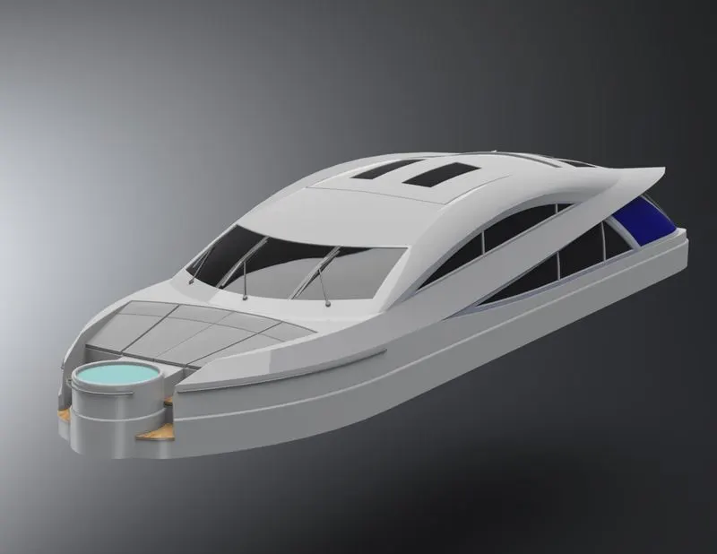
Super structure:
A superstructure is an upward extension of an existing structure above a baseline. This term is applied to various kinds of physical structures such as buildings, bridges, or Ships having the degree of freedom zero.
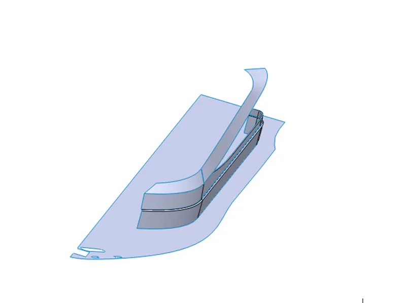
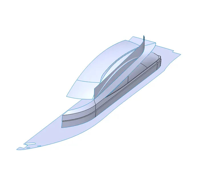
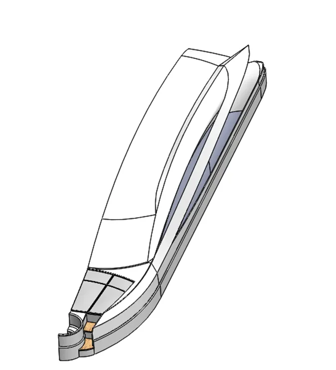
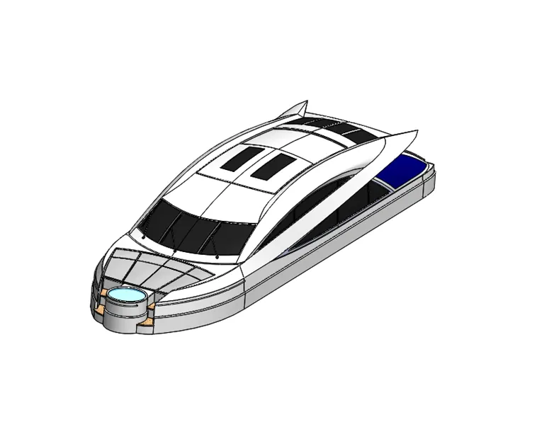
Rendred image:
Features Used:
Sketch
Lofted surface
Surface trim
Extrude surface
Surface Knit
Surface fill
Extrude Boss
Extrude Cut
Fillet
Chamfer
Reference plane
3D Sketch
Swept Boss
Revolved Boss
Dome
Linear pattern
Delete face
Mirror
Combine
Split
Offset surface
Thin Extrude
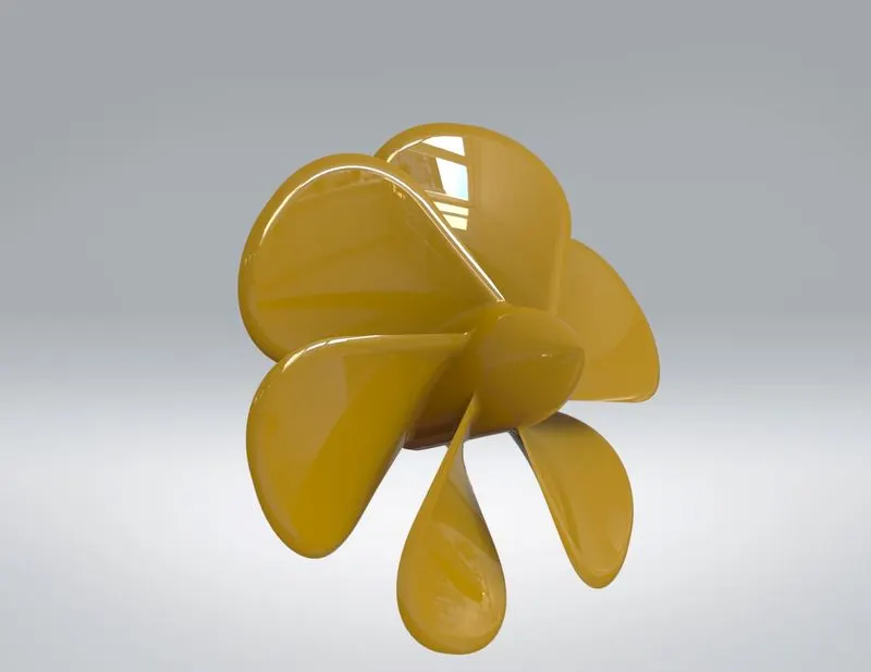
Propeller:
A propeller is a rotating fan-like structure which is used to propel the ship by using the power generated and transmitted by the main engine of the ship. A ship can be fitted with one, two and rarely three propellers depending upon the speed and maneuvering requirements of the vessel.
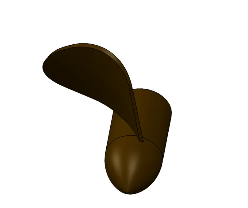
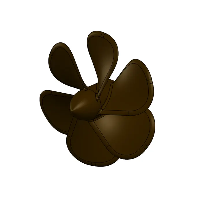
Rendered Image
Features Used:
Sketch
Revolved Boss
Extrude Cut
Fillet
Reference plane
Lofted boss
Circular Pattern
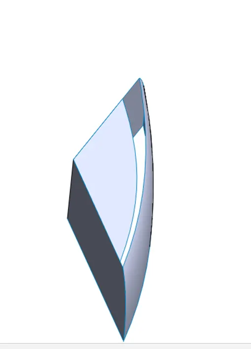
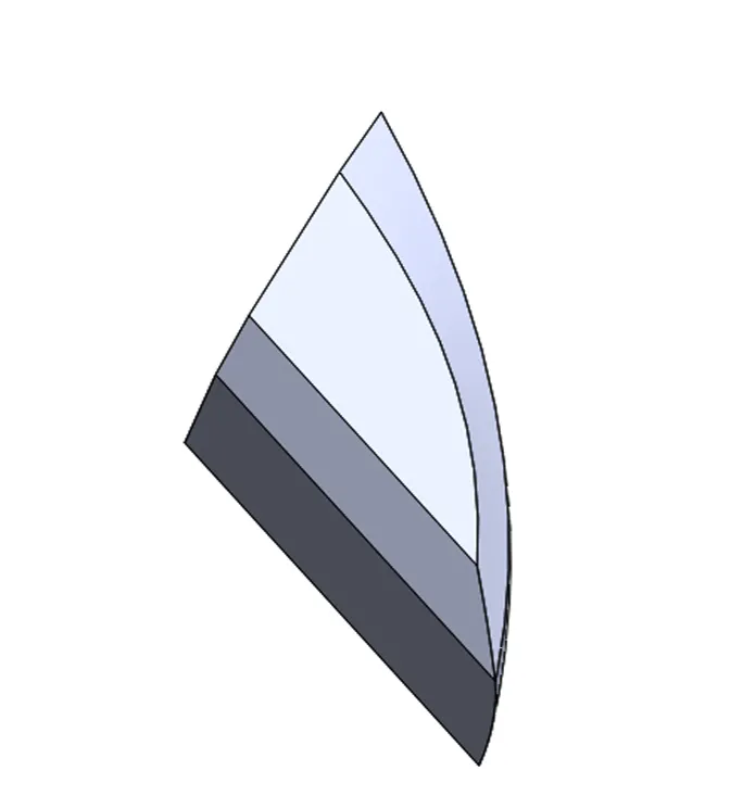
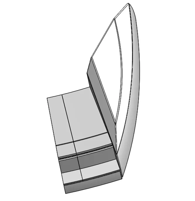
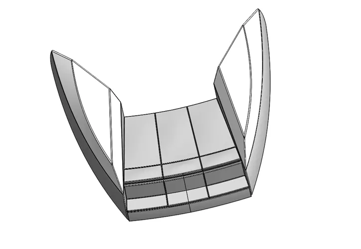
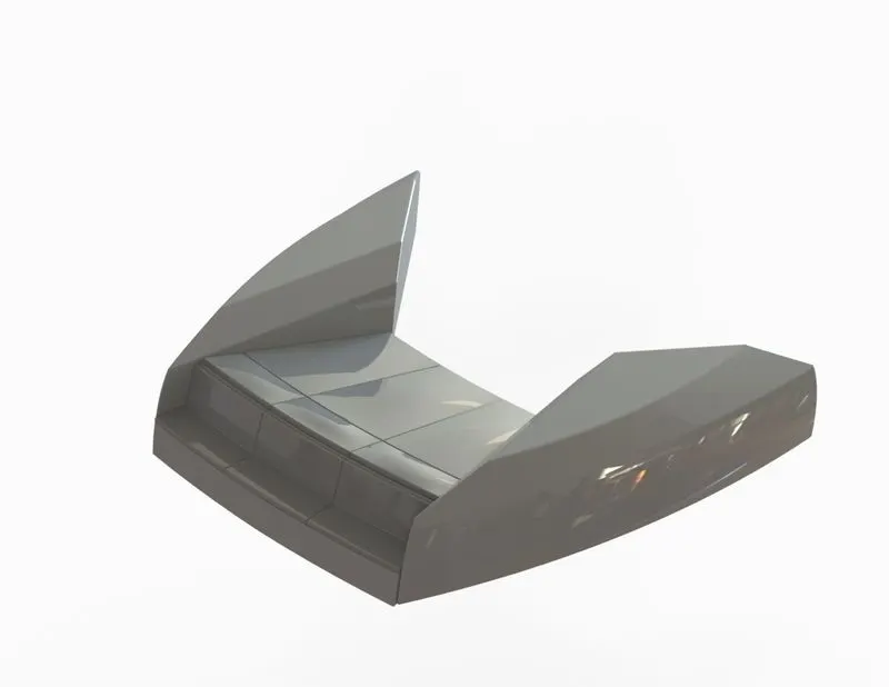
Front seat:
Front seat of yacht is used to sit in the front side of yacht.
Rendered Image:
Features Used:
Sketch
Reference plane
Lofted surface
Surface trim
Extrude surafce
Surface Knit
Surface fill
Extrude Boss
Extrude Cut
Fillet
Chamfer
Swept Boss
Revolved Boss
Dome
Mirror
Combine
thin Extrude
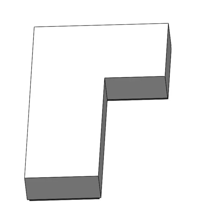
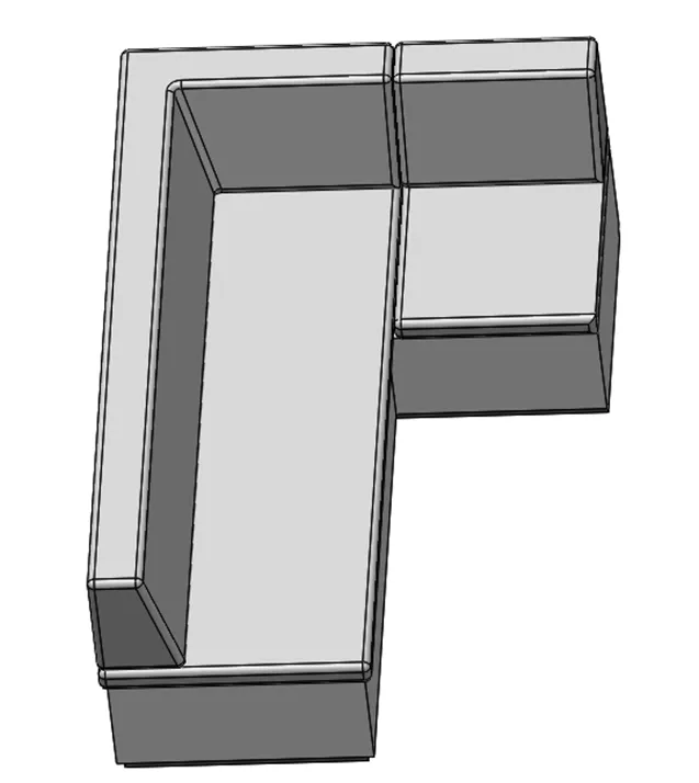
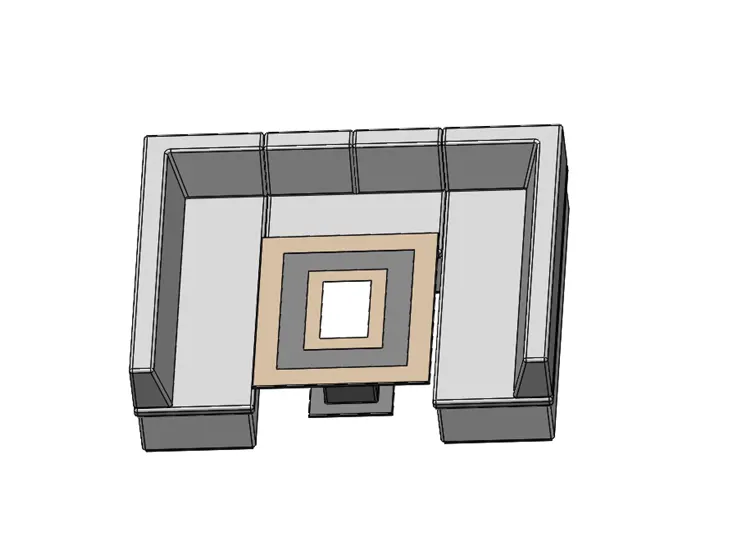
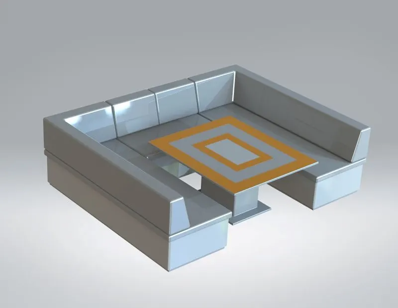
Middle seat:
Seating arrangement provided in middle of the yacht.
Rendered Image:
Features Used:
Sketch
Extrude Boss
Extrude Cut
Fillet
Chamfer
Mirror
Rear Seat:
seating arrangement provided back of the yacht.
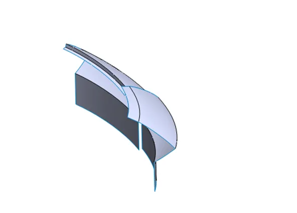
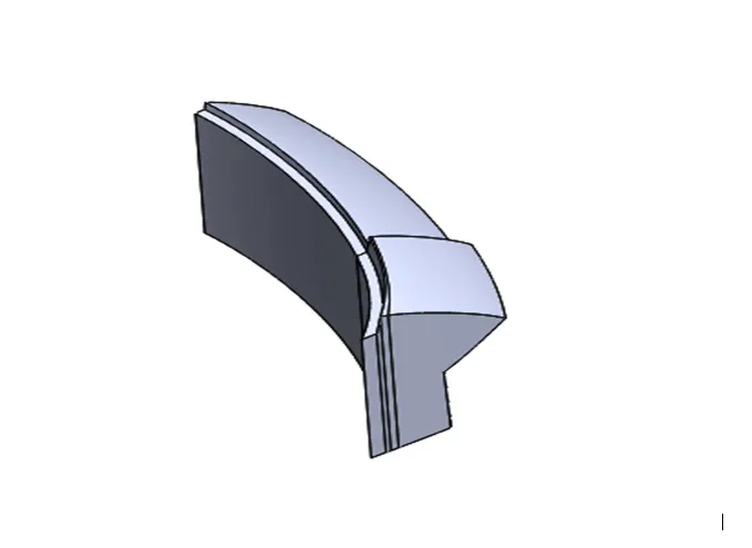
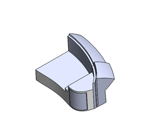
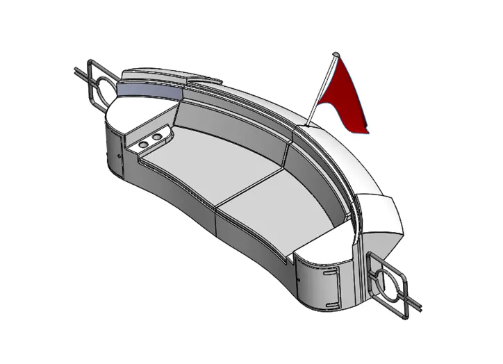
Redered Image:
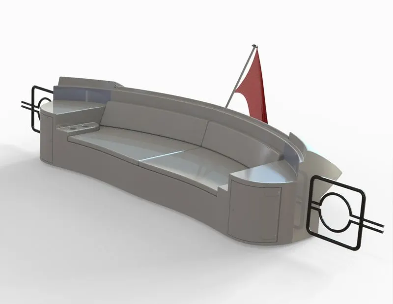
Features Used:
Sketch
Reference plane
Lofted surface
Surface trim
Extrude surafce
Surface Knit
Surface fill
Extrude Boss
Extrude Cut
Fillet
Chamfer
Swept Boss
Revolved Boss
Dome
Mirror
Combine
thin Extrude
Radar:
Radar is a vital navigation component for safety at sea and near the shore. Captains need to be able to maneuver their ships within feet in the worst of conditions and to be able to navigate "blind", when there is no visibility at night or due to bad weather.
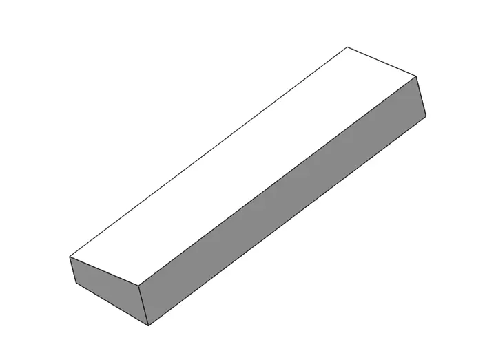
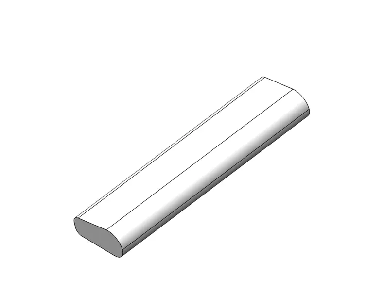
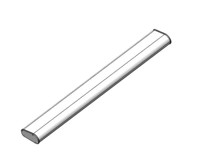
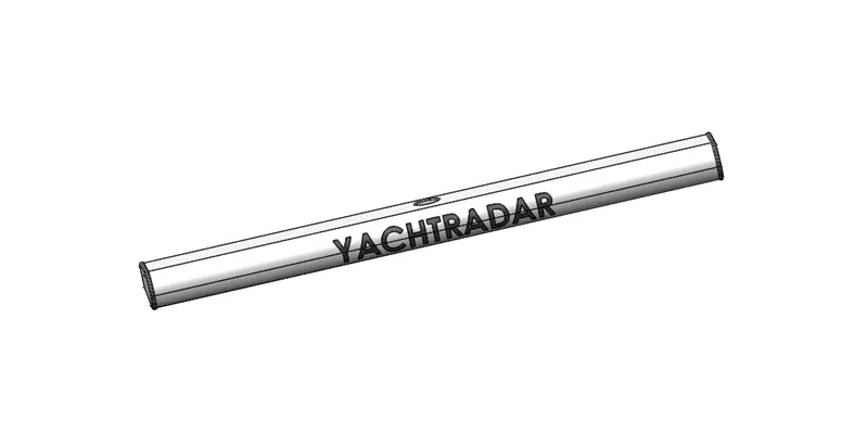
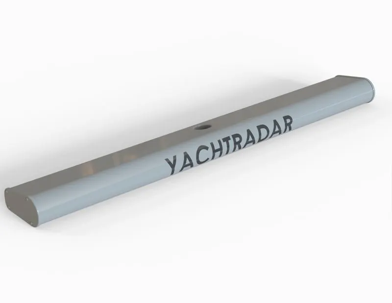
Features Used:
Sketch
Extrude Boss
Fillet
Mirror
Extrude Cut
Sketch driven Pattern
Split Line
Radar mast:
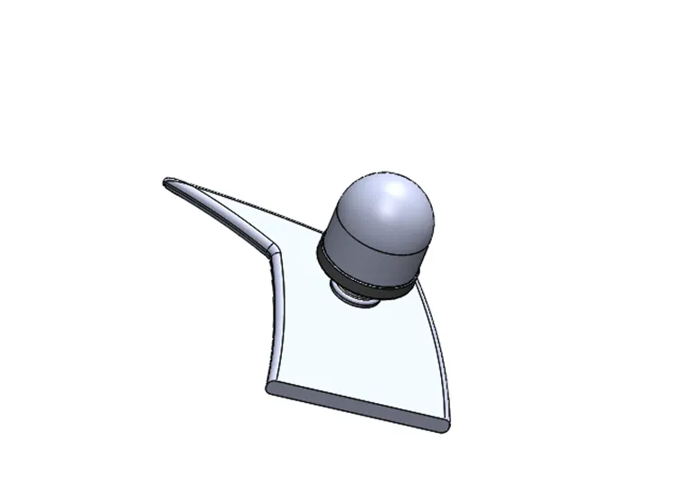
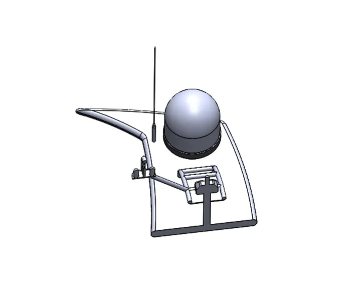
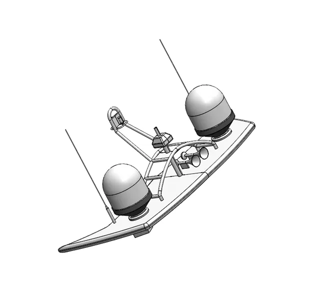
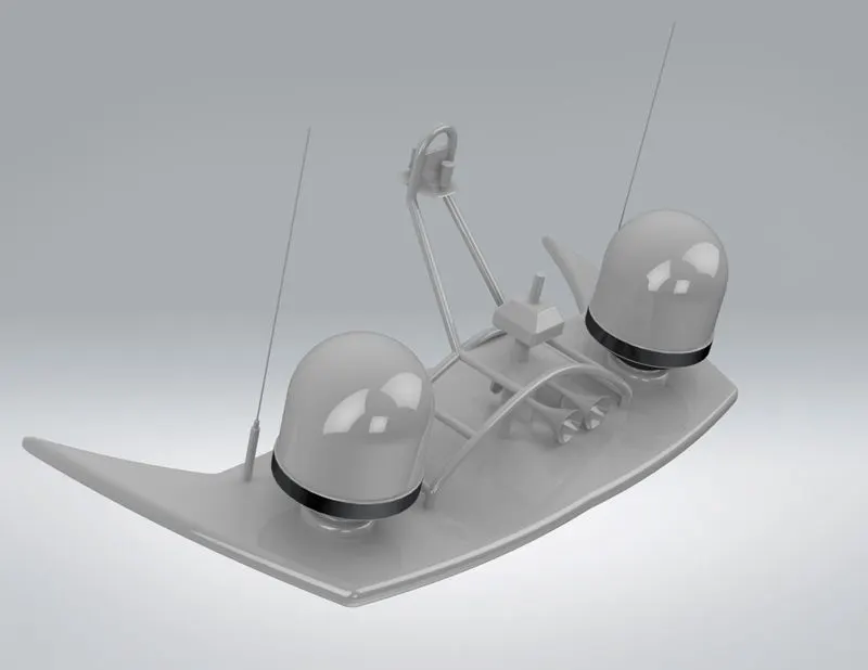
Radio Detection and Ranging, is used to detect objects and their position relative to your current location. It works by sending out a radio signal. When the signal hits an object, it gets reflected back to the radar, which can then calculate a rough estimate of the object. It does so by detecting other ships and land obstacles, to give bearing and distance for collision avoidance and navigation while on water.
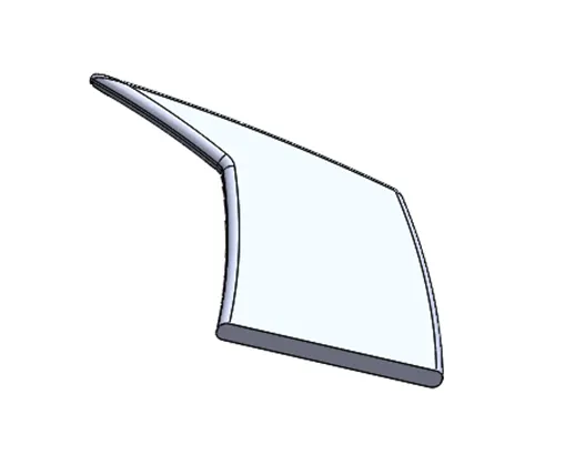
Features Used:
Sketch
Reference plane
Extrude Boss
Fillet
Chamfer
Swept Boss
Revolved Boss
Projected Curve
Dome
Mirror
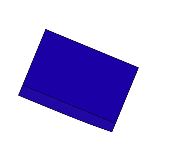
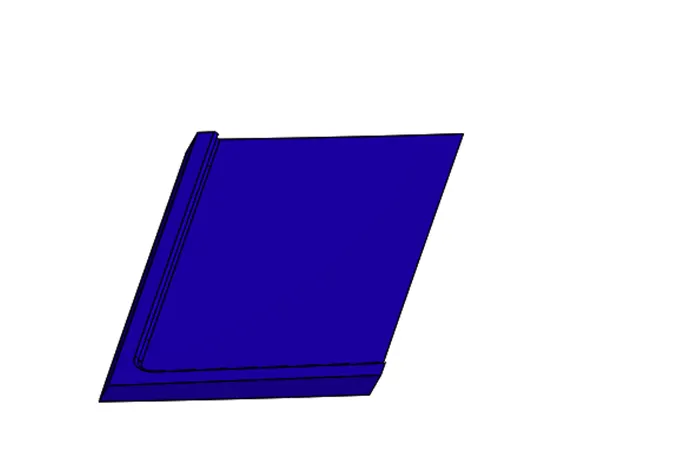
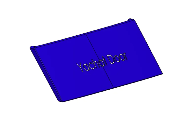
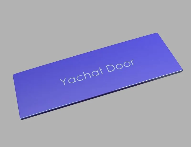
Garage Door:
It is back door provided for parking
Features Used
Sketch
Extrude cut
Fillet
Mirror
Split
Shell
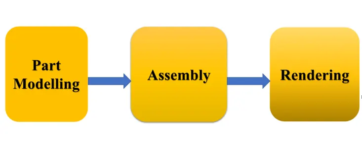
Assembly
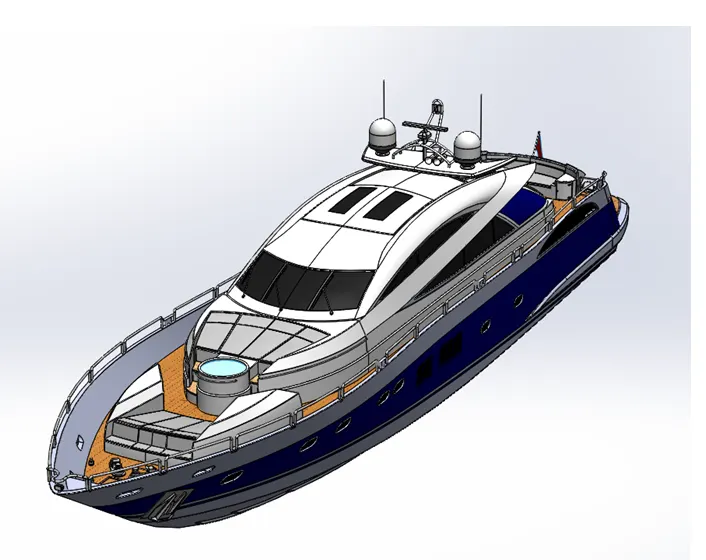
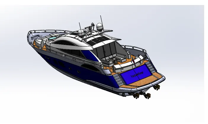
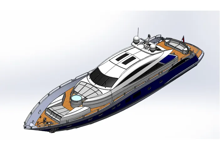
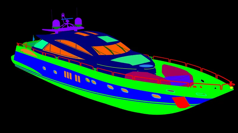
Assembly is the process of putting together components on an assembly line. In addition to this, it also refers to an assembled product or part made in this way. In either case, mechanical assembly carries the connotation of putting parts together, making a complete product to perform a function.
Rendering
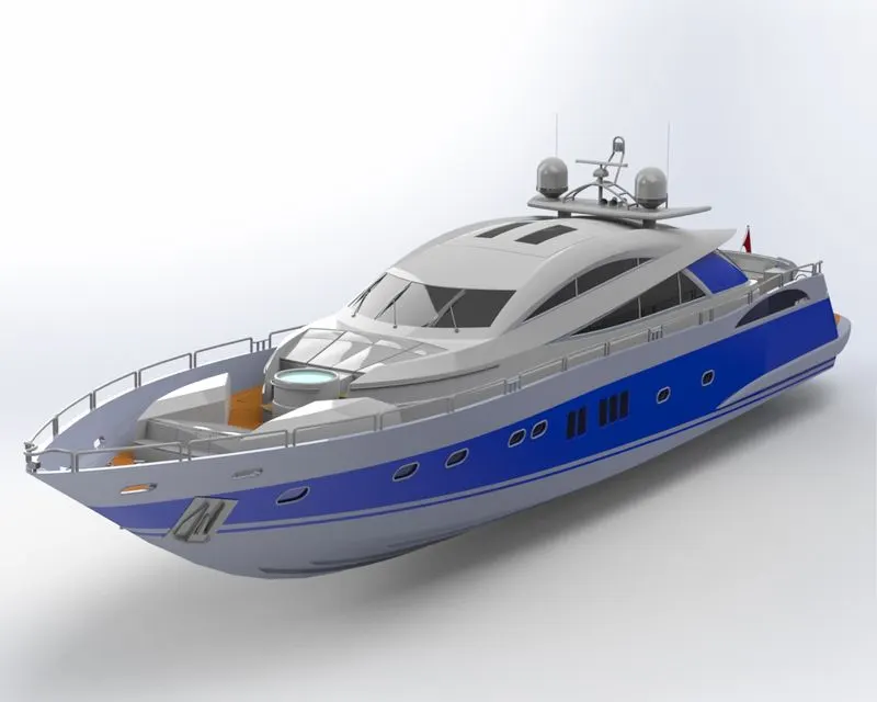
Rendering is the process of generating a photorealestic image from a model. The resulting image is referred to as the render. Multiple models can be defined in a scene file containing objects in a strictly defined language. The scene file contains geometry, viewpoint, texture, lighting, and shading information describing the virtual scene. The data contained in the scene file is then passed to a rendering program to be processed and output to a Rendered image file.
Conclusion:
Complete assembly of yacht including part modelling and assembly and rendering completed using solid works,solidworks visualise and key shot