Week 8 - Challenge 2 - Base Bracket Design
AIM : To create a base bracket using a given class-A surface
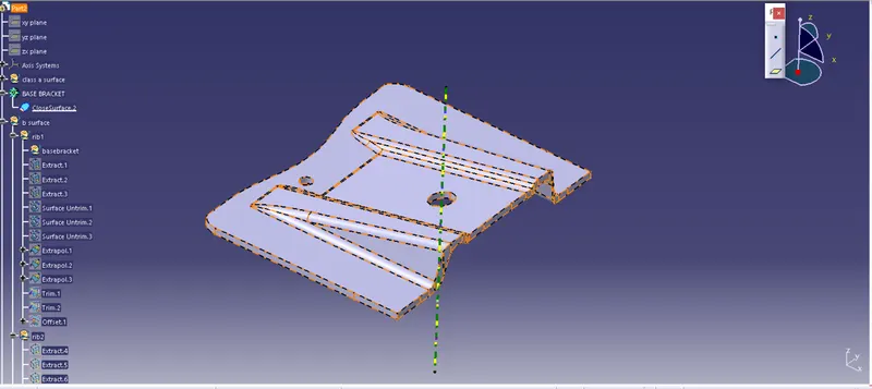
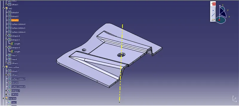
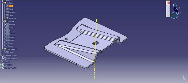
GIVEN CLASS A-SURFACE
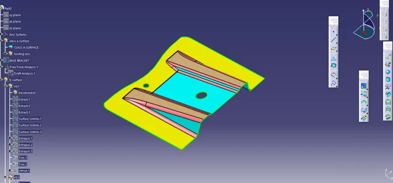
FINAL CLOSED SOLID-BODY
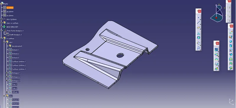
TOOLING AIXS :
first class-A surface Is analyzed to create tooling axis direction.
- the reference point is created on the extracted surface
- new axis system is made on the reference point
- the x and y directions were used to create the tooling axis
- a single bisecting line was created using the two clearance lines made on the reference boundary
- change the properties of the tooling axis and publish it along with the class a surface
DRAFT ANALYSIS
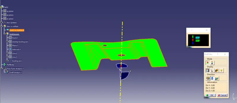
- The Draft Analysis command enables the user to detect if the part that the user drafted will be easily removed.
- This type of analysis is performed based on color ranges identifying zones on the analyzed element where the deviation from the draft direction at any point, corresponds to specified values.
IMPORTANT NOTES
- nominal draft angle is 3degree
- 5 degrees can also be used but it increases the draft angle
- 7degree is used for a textured surface
PROCEDURE
- first, check if the model is in material mode
- then click on analysis and select feature draft analysis
- select the compass and align it with the tooling axis created before
- now green color will appear on the model which signifies that it can be made under the given draft angle
- we can change the draft angle in the color tab by double-clicking it .. optimum draft angle is 3degree
DRAFT ANALYSIS ON SOLID PART
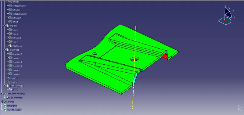
IMAGES FEATURE TREE