Week 8 - Challenge 2 - Base Bracket Design
BASE BRACKET CREATION
Objectives:
- To conduct draft analysis on the given class A surface of the base bracket
- To generate class b and class c surfaces with proper drafts at edges.
- Finalizing the solid model from the surface part using part workbench.
Software used: DS CATIA P3 V5 - GENERATIVE SHAPE DESIGN, PART DESIGN WORKBENCH
Introduction:
In this project I'm going to create a base bracket solid element from a class a surface part. The first aim of this project is to check whether the part is applicable to the molding process. For that, we need to conduct draft analysis on the surface. Then we will be doing the solidification work process with ensuring process draft angles at all boundary edges of the part.
Draft analysis: Drafts are a type of modification that is usually given to product design for the application of manufacturing. It ensures proper removal of the product of the molding process without sticking to the core and cavity. For this, we provide slanted edges at the sides of the product being designed. In CATIA, we have a tool called draft analysis to check if the product is feasible enough for the molding process. It checks every edges and slanted surfaces for draft angles and gives output as shifting in coloures where the draft angles are accepted or not.
Design methodology:
Step 1:
Continuity check: Use join or boundary command to check for open boundaries on the part model. If the boundaries only exist at proper edges only, the surface is accepted.
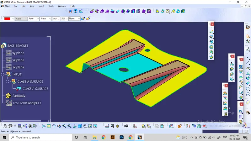
Different colors are provided for different surfaces for diversification.
Step 2: Tooling axis creation:-
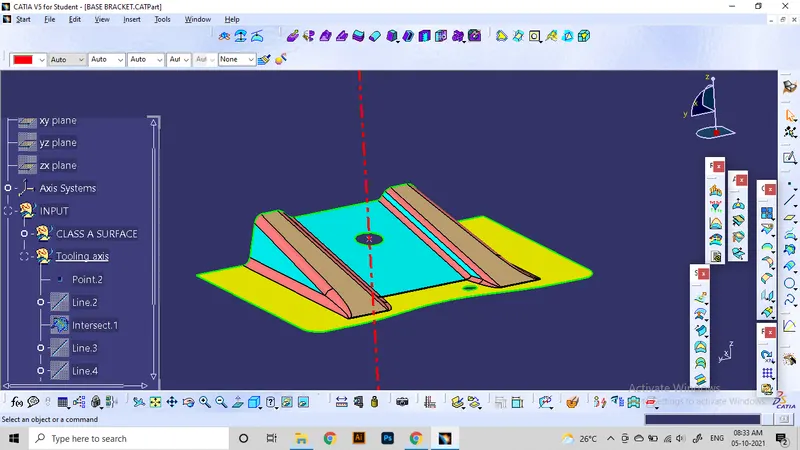
By analyzing the surface, we can see that it's good to use the z axis as tooling axis. For the other axes, we might require side cores for the generation of holes. And the design is symmetrical about ZX plane. For better placement, tooling axis is provided on the Large hole at the center.
Creating A dummy tooling axis passing through the center of the hole
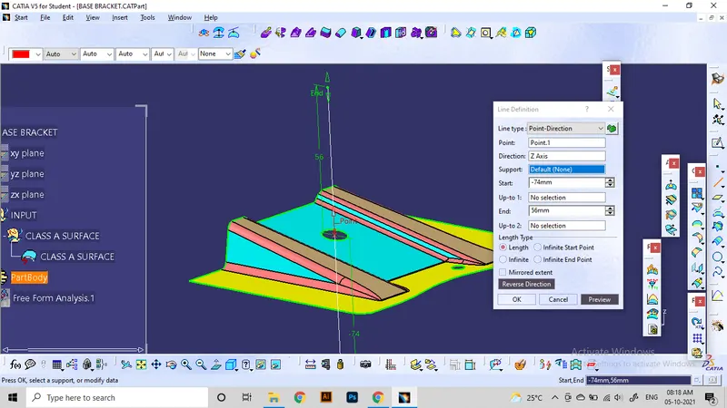
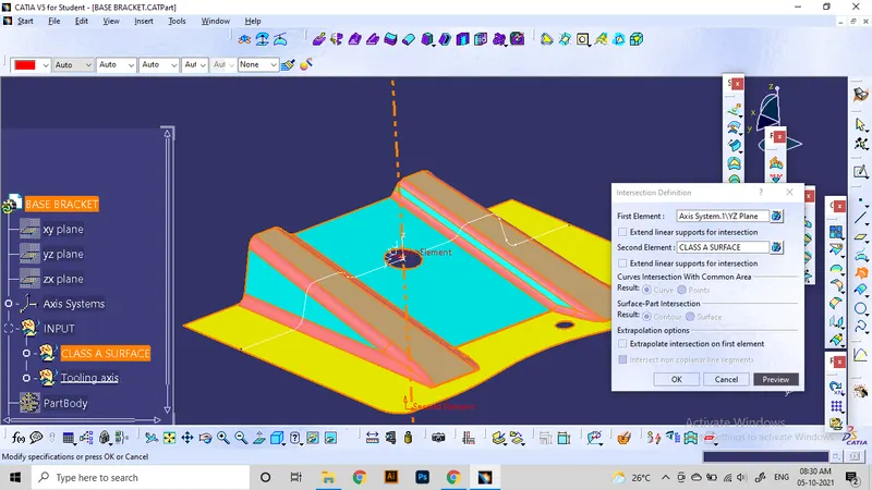
Then intersecting the surface in zy plane to get the curvature properties of the surface. For that, we need to make an Axis system at the center of the hole.
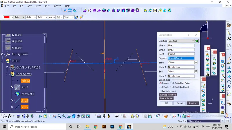
Just like the previous project, Tooling axis is created by bysecting the slanted surfaces. The process is shown below. For a properly symmetrical element, the Tooling axis will pass through exactly center of the hole.
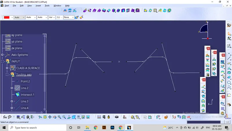
Extent the slanted lines and Bysect them using bysecting line option in the line definition tool. provide 2 slanted edges and the center point of hole as input. The resulting line can be considered as the tooling axis.
Step 3: Draft analysis:
In catia, The result of this analysis is produced as colored Visualization. For conducting the draft analysis, use the tool, Insert->Analysis->Feature draft analysis or click the corresponding icon at toolbar.
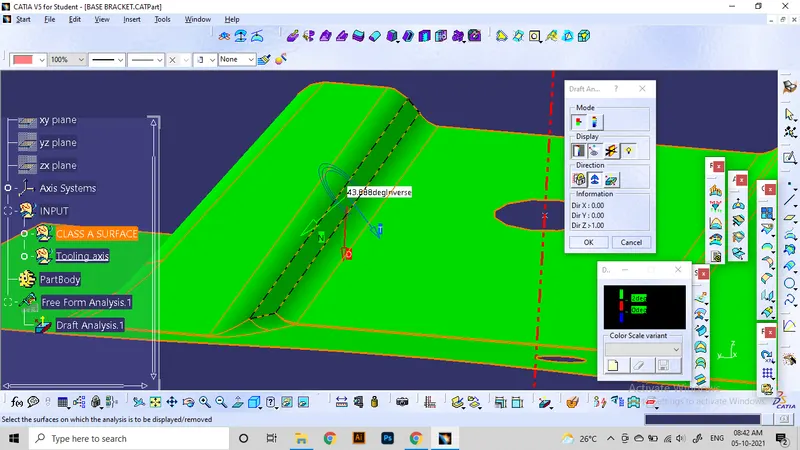
The first symbol showing is for the quick analysis option, it is used to check quickly for the given value of the draft angle if provided on the design. initially, we need to enable the compass in the direction tab to set the direction of the tooling axis. Move the compass to the tooling axis by picking the red dot and align it to the tooling axis where, the w direction of compass comes inline to the axis.
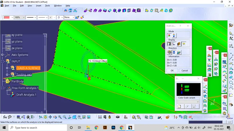
Normally, Clicking the part will show the color green where draft angle is ok and red if the angle is 0, and blue if the angle is negative. we can change the color and the value of draft angle to be checked in the window shown below the draft analysis toolbox. To enable or disable the color scale, use the first tool in display tab.
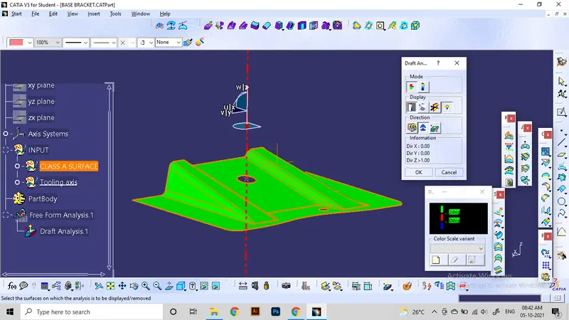
Here, the surfaces are checked to be ok for draft analysis. All slanted surfaces shows positive drafts.
Step 4: Class B surface generation
The inside surface of the solid component of a Class A part is considered as Class B surface. All of the support elements and fixations the usually provided on the class B surface. Since the class A surface is aesthetically and ergonomically designed. In this project I'm using the class A surface to offset a Class b.
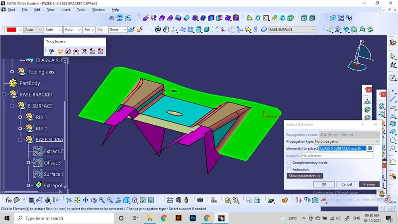
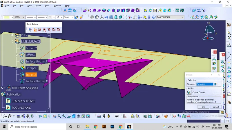
Each surfaces that made the class A, needs to be taken out of the part. And all of them undergo the process of Extraction, Untrimming, Extrapolation, and offsetting to generate the required patches for the class B surface as shown below.
First starting with the Rib areas.
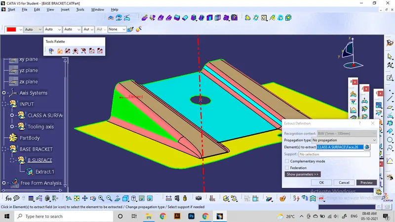
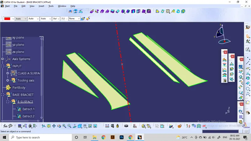
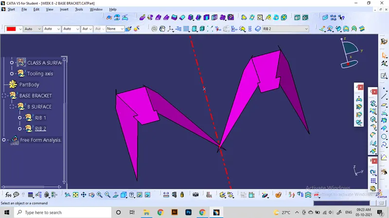
Taking one Rib for initial processing,
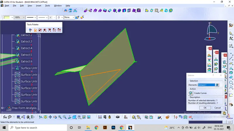
Untrim command shows the surface that used to trim the class A.
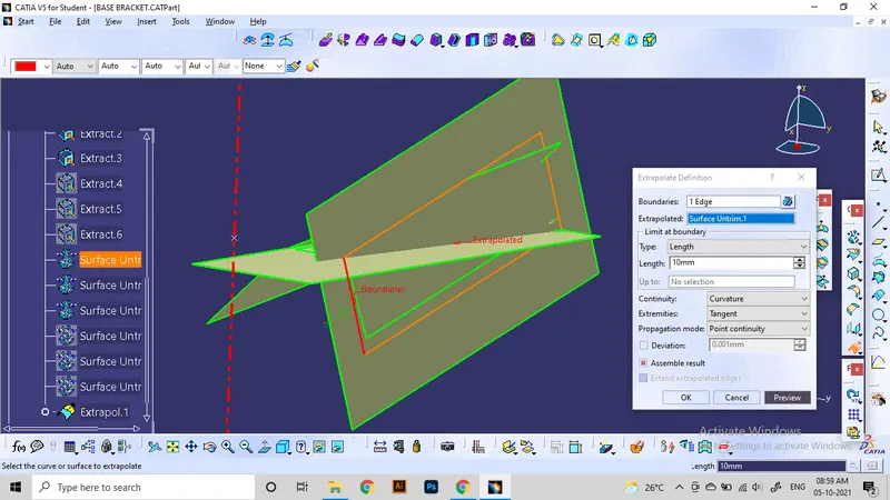
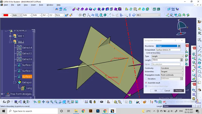
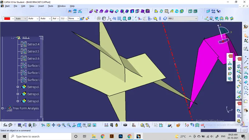
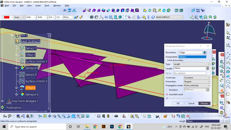
Extrapolation is used to extent the boundary of surface to ensure the intersection between the near surfaces. Use point continuity for extent full boundary at the length of 10mm.
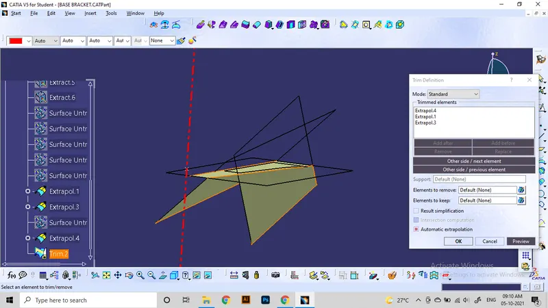
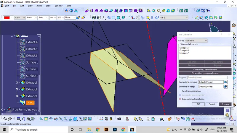
After that, The extended surfaces will be trimmed as shown in figure.
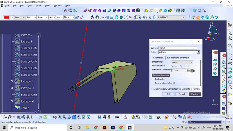
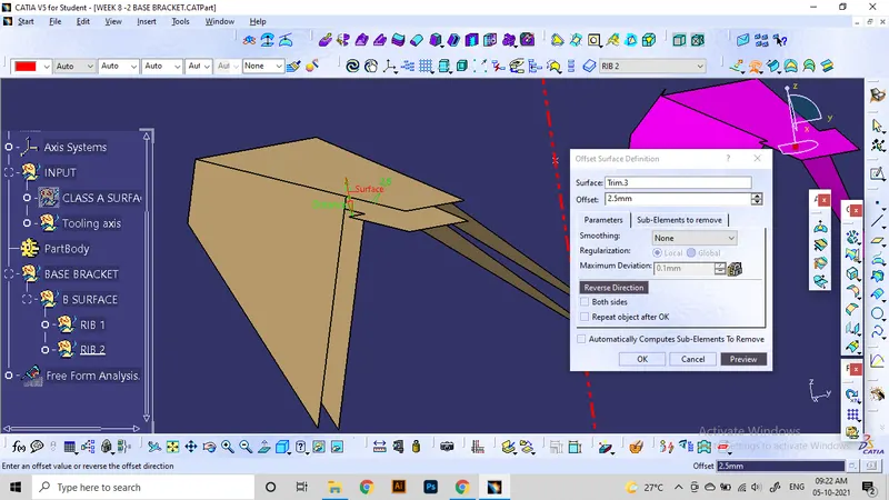
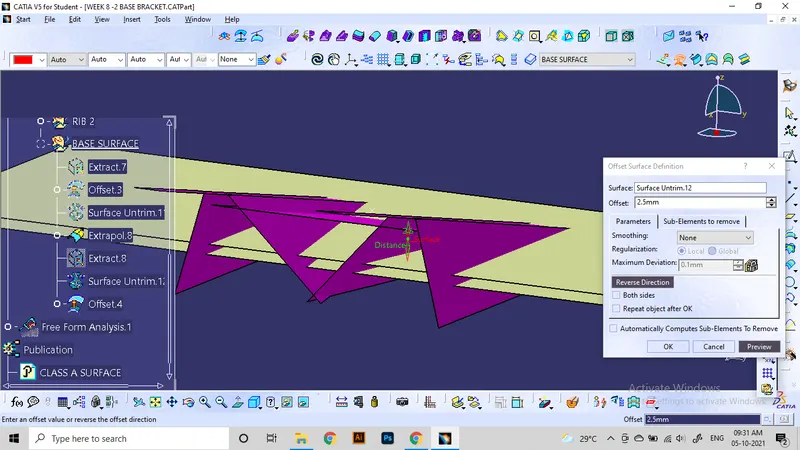
To form the rib part for Class B surface, use offset command on the currently made rib. The thickness of solid part estimated to be 2.5mm.
Repeating the same for other rib.
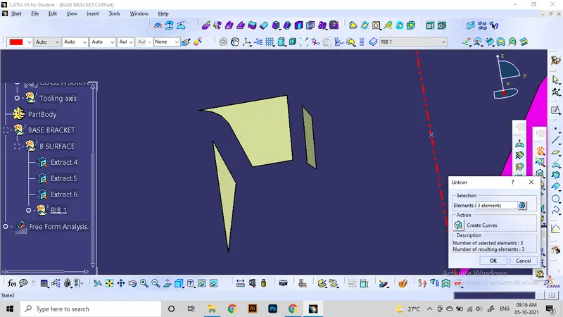
Now use similar method to extract the plane surfaces also. And offsetting them will create all patches needed for the class be surface.
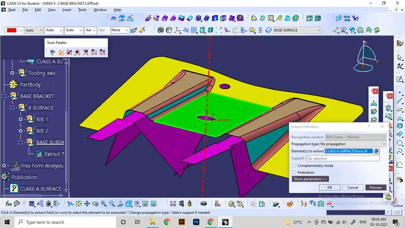
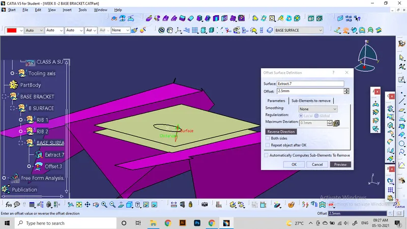
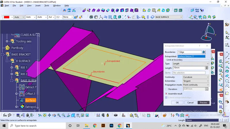
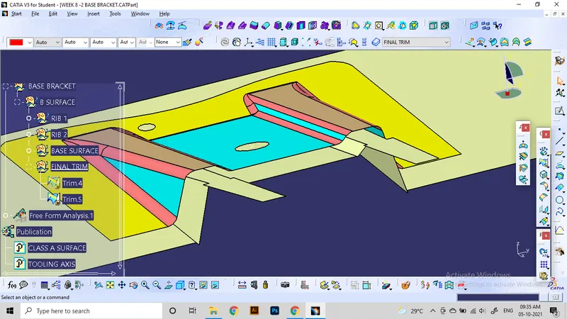
Now use trim command to trim the patches into 1 single patch used for class B.
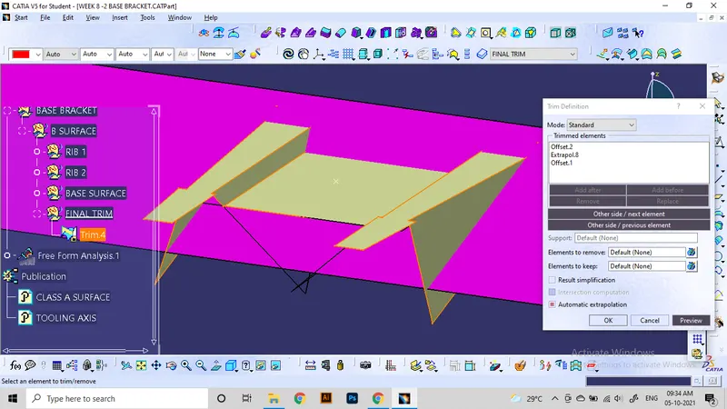
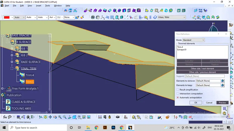
Figure shows the class A and B surfaces with proper offsets.
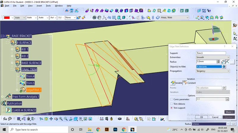
Now it's time for filleting the all required edges of class B. Fillet radius is calculated as the addition of fillet radius of the class A surface and thickness of the part.
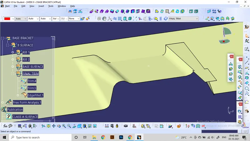
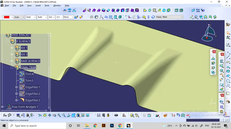
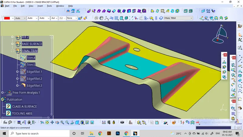
step 5: Class C surface
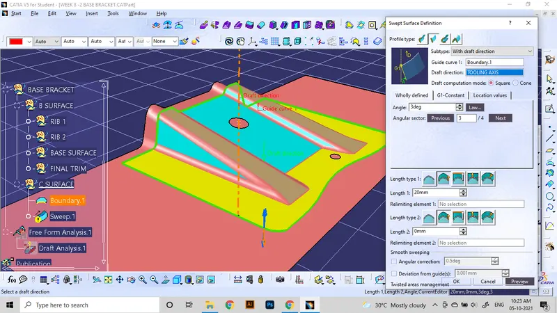
The edge extensions Connecting the class A and B are known as Class C surfaces. Drafts are required to provide on this surface. For making this, we need to define the boundaries of class A surface.
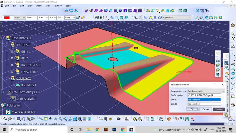
This boundaries used to draft the C surfaces using Sweep command with draft diretion option. Inputs are provided as shown in the figure. draft angle is 3 mm.
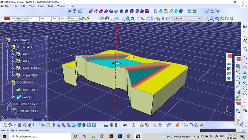
Also define boundaries at holes to draft them along the tooling axis.
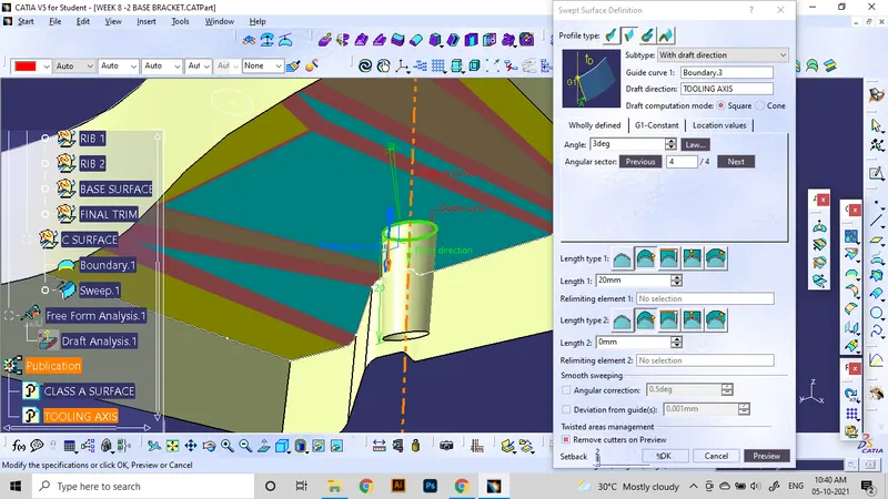
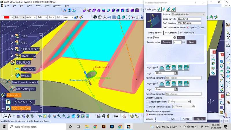
Drafted parts can be joined together using join command as shown.
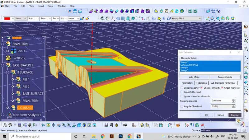
Step 6: Joining all surfaces and finalizing the part:
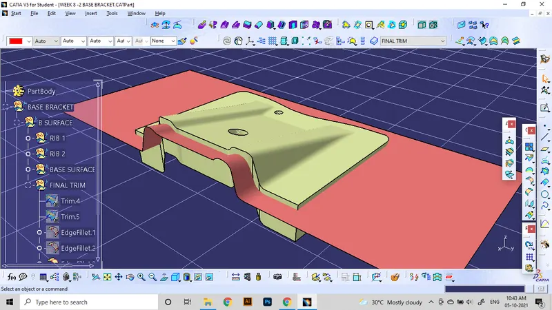
Now, unhide the Class B surface and use it to trim with the class A and C part. It results in making a single element with proper drafts and thickness as required.
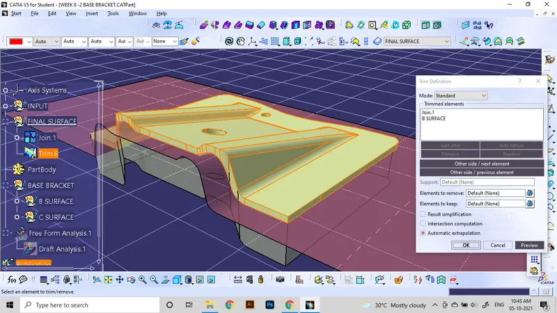
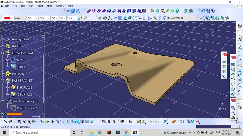
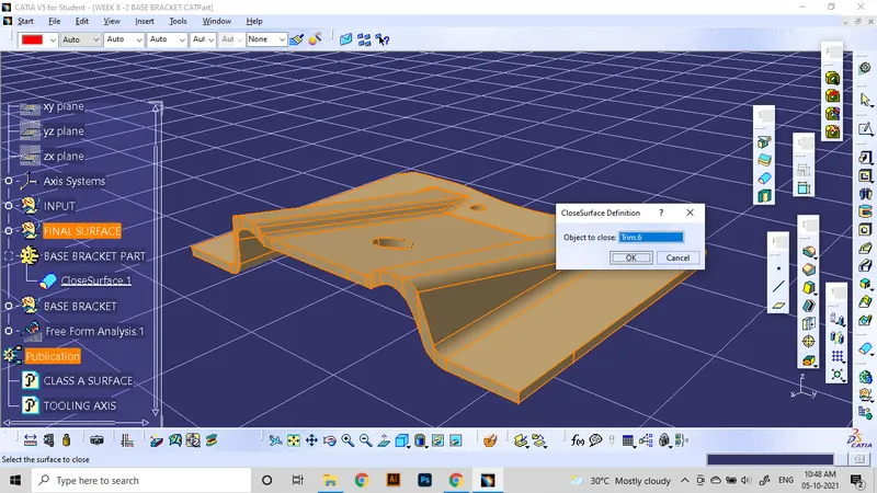
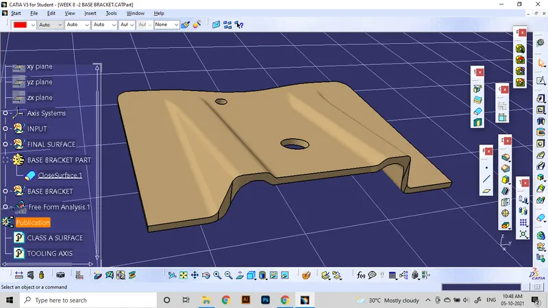
Now go to the Part workbench, Insert a new Body, and use close surface to make a solidpart out of the surface geometries.
Conclusion: Hence studied to Conduct draft analysis on a class A surface and practiced the method of creating Class B and C surfaces from a given Class A part.