Week 8 - Challenge 2 - Base Bracket Design
Objective: To design the class B & C surface for the given the base bracket class A surface using Catia V5R21 and to perform the draft analysis.
Procedure:
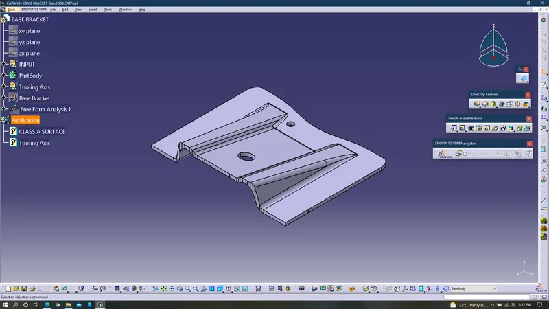
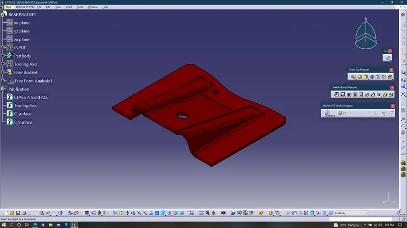
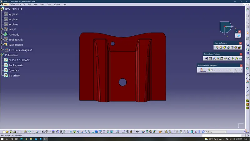
The above image shows the solid part of the base bracket, to create it following procedure must be followed:
1. Obtain Class A Surface and perform connectivity check, to inspect the surface whether it contain any flaws(gaps) between them.
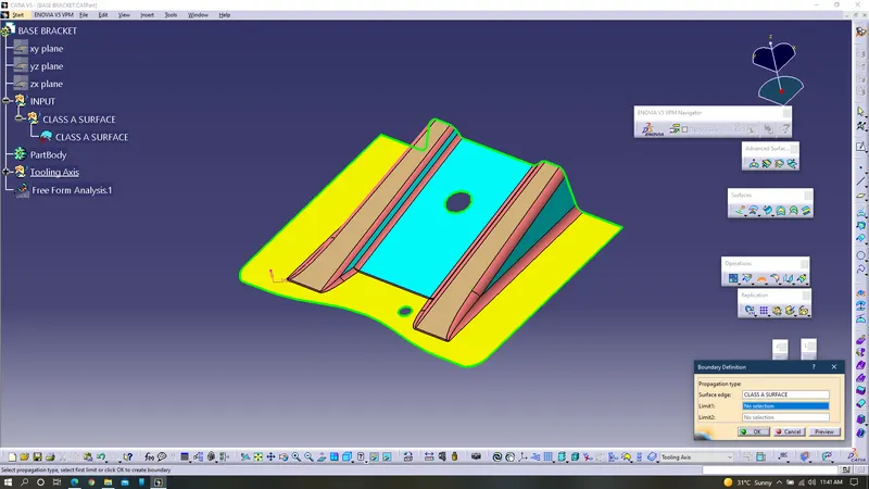
2. After ensuring the connectivity check create a point at the circle to perform draft analysis for class A surface.
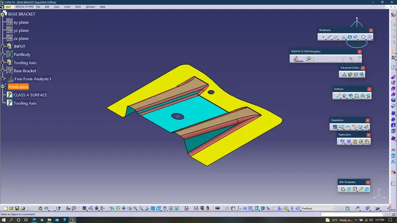
3. Next step is to create a plane using the point which has been created.
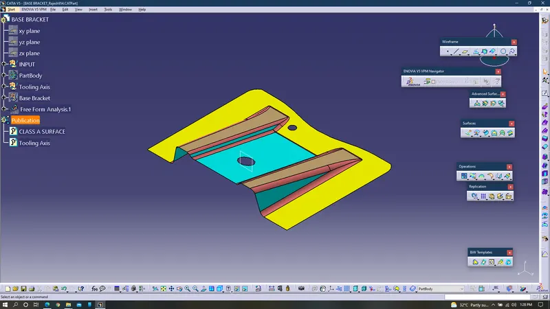
4. After creating plane with the help of intersection curve command create a intersection curve on the plane by selecting the required surfaces.
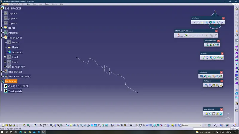
5. Next step is to create tooling axis with the help of bisecting lines command.
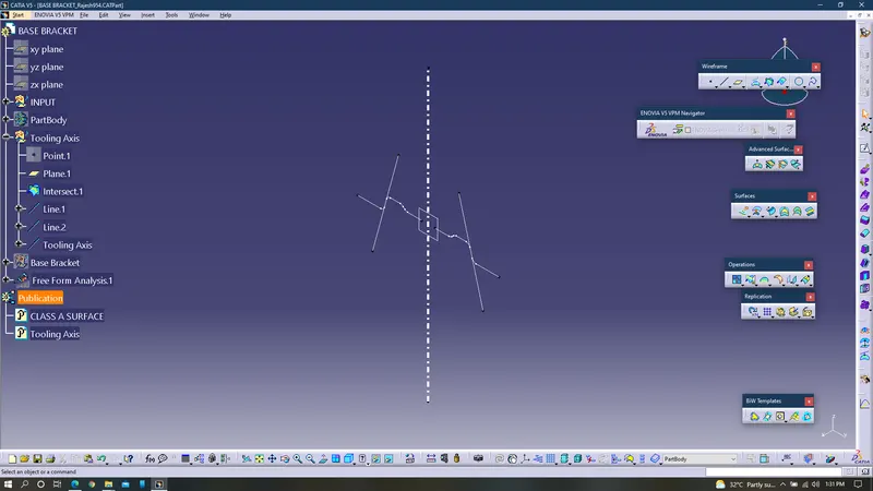
6. After creating tooling axis perform feature draft analysis on the class A surface.
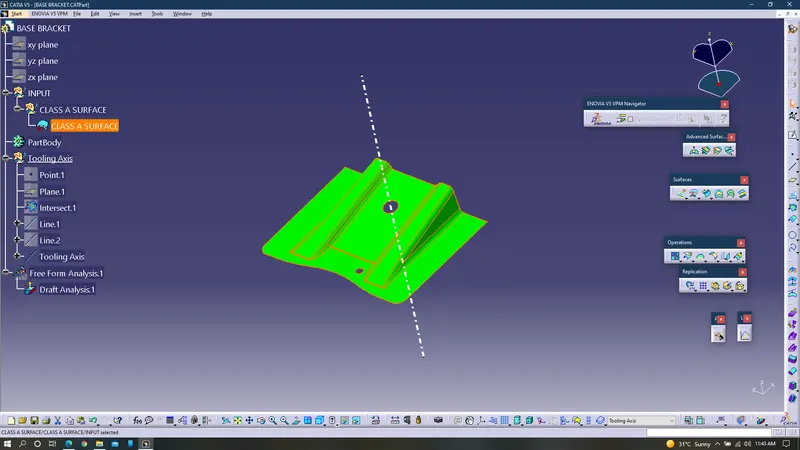
7. Next step is to create class B surface which is also known as engineering surface, where all the fittings to be made by this surface. Class A surface is known as asthetic surface where there will no operations on those surfaces. To create class B surface extract the rib surfaces using extract command.
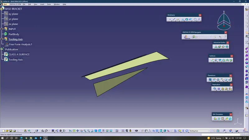
8. Untrim those surfaces and extrapolate them by selecting the edge of the surface and by selecting the sheet with point continuity.
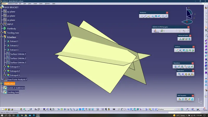
9. Trim the excess portion of the sheet and offset them to create class B surface.
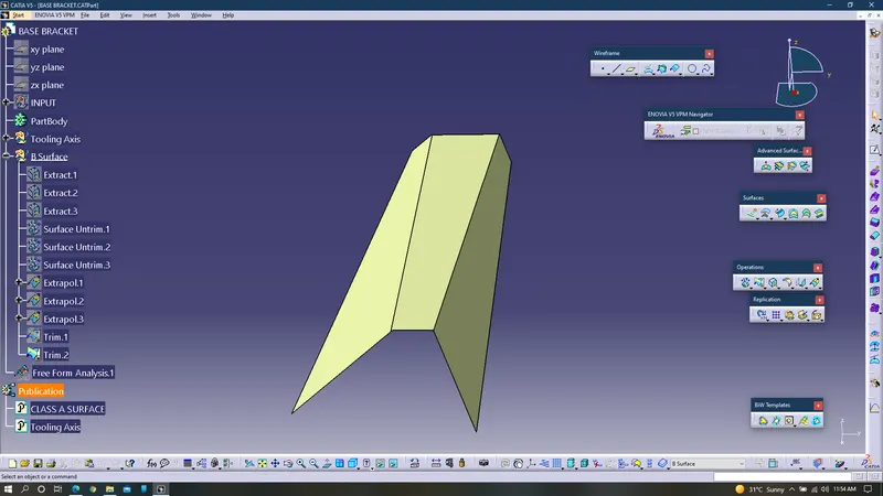
10. Follow the same procedure for the other too.
11. Furthur step is to extract the base surface of the class A surface of base bracket.
12. Untrim those surfaces to remove any gaps on the surfaces.
13. To ensure this we can perform connectivity check using boundary command.
14. Next step is to offset them to create class B surface, in all the cases 2.5mm offsetting distance has been applied.
15. Extrapolate them and use trim command to create the exact profile required for the base bracket.
16. Provide required fillets using edge fillet command, in all the cases 3mm fillets were provided to the surfaces.
17. Create class surface using sweep command by selecting draft direction, choose the profile which has to be swept which is the profile obtained by using the boundary command. Select the profile and choosing the direction as tooling axis and create the class C surface.
18. Holes provided on the class A surfaces must be extracted using boundary command. This povides profile and this profile must be swept using sweep command by selecting draft direction as tooling axis.
19. Join both class A and C surfaces.
20. Remove the excess portion of the class C surface and B surface using trim command by selecting the join which has been created and class B surface.
22. Convert the surface into solid, to create it enter into part design module and with the help of close surfaces command create the surface into solids.
23. Perform draft analysis.
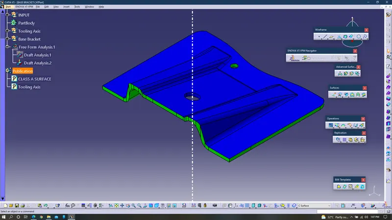
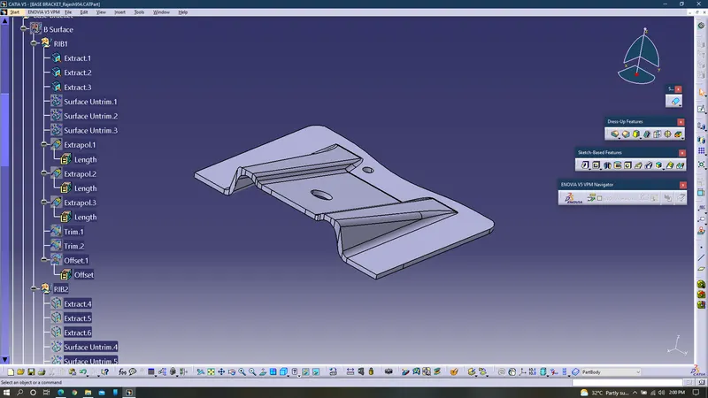
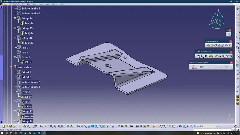
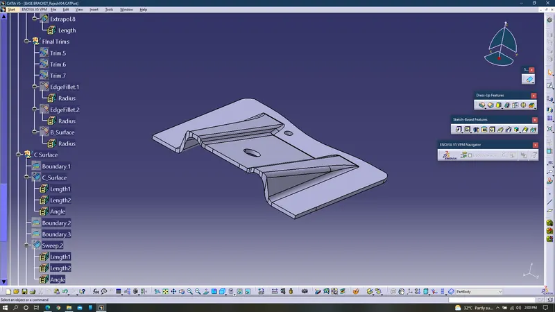
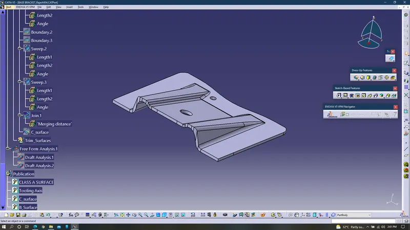
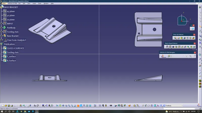
Feature Tree Diagram of Base Bracket:
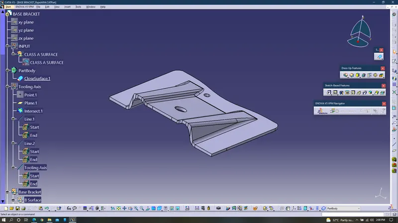
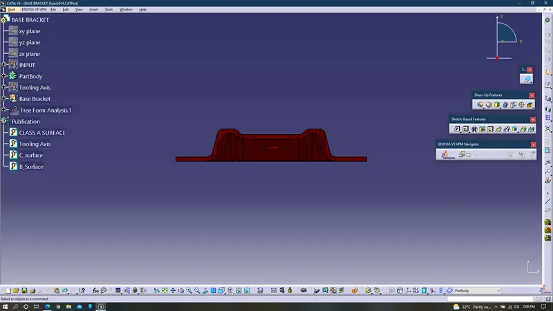
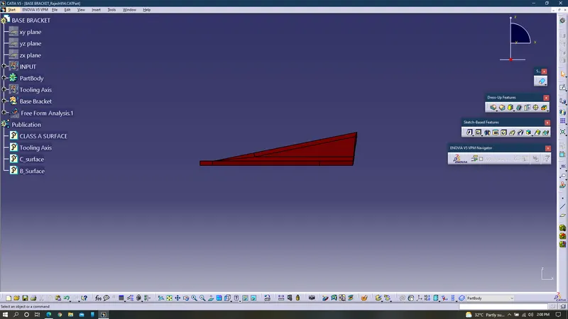
Views of Base Bracket:
Conclusion:
Class B and C surfaces has been created and performed draft analysis for the given class A surface and whole component.