Week 8 - Challenge 2 - Base Bracket Design
AIM:
To create a tooling axis for a component and perform the draft analysis along the tooling direction
OBJECTIVE:
Ensuring the feasiblitiy of manufacturing procedure without any frictional damage, wear rate to the component by creating a centre tooling axis and adding draft angles for smooth ejection.
SOFTWARE USED: Catia V5
COMPONENT:
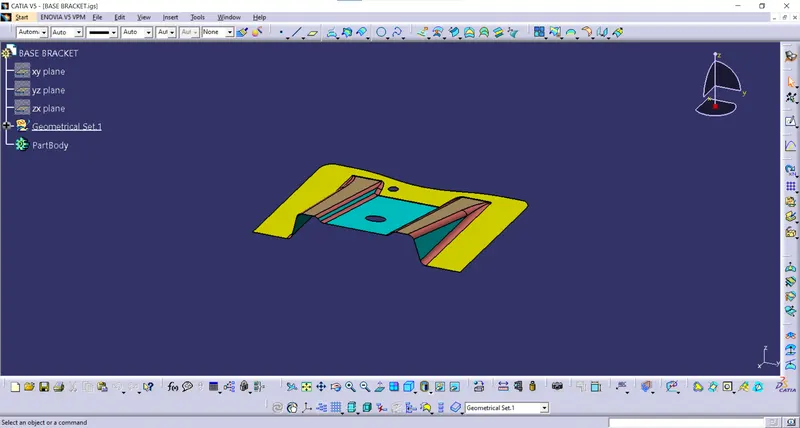
Base bracket
DRAFT ANALYSIS:
Intially, once after the visual inspection along with the join and boundary conditions are checked, a dummy tooling axis is created with the center point along the Z-direction.
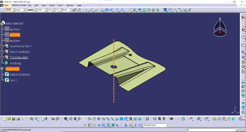
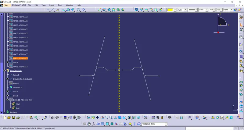
Then a intercept along the YZ plane is taken out and made the profile to intersect with the plane giving the Y intersection profile. Then a bisecting is line is created giving the definite tooling axis from the two inclined profiles.
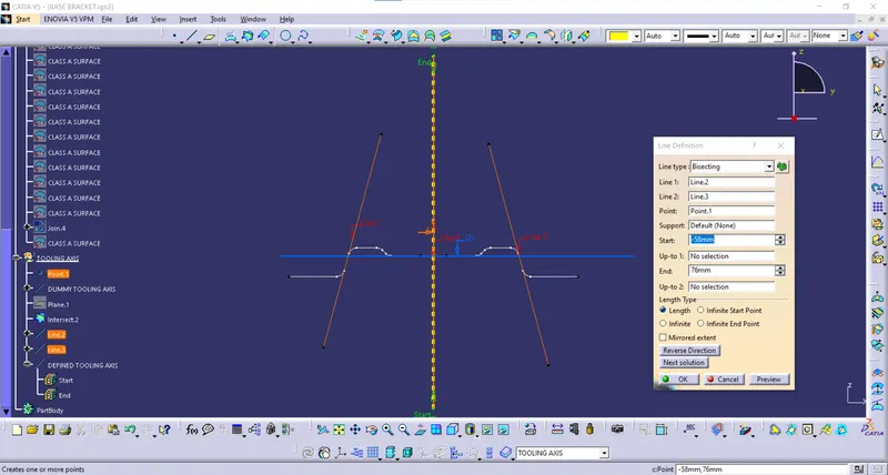
Then draft analysis is carried out along the definite tooling axis. As said earlier a minimum of 3deg for the external profiles is provided for the feasibility.
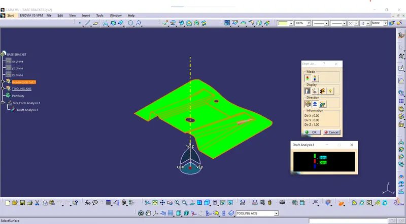
Along with it the profile angles can also be inspected for ensurity.
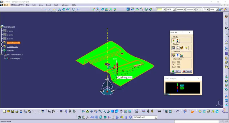
CREATING B SURFACE:
The class A surface is for the look and feel aesthetic purpose while the B surface has the engineering aspects. All the definitions for the component to be rigid, fixations, and rest all engineering features are defined in this surface. The steps are as follows:
Both the ribs are being extracted, untrimmed, extrapolated and trimmed to form the replicate of class A surface with the extract, untrim, extrapolate and trim commands respectively.
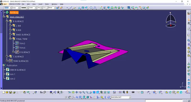
Then the bases are extracted the same way and then extrpolated after being offset to the thickness of the component.
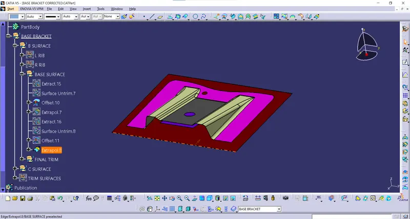
Then they are trimmed together to form the respective profile
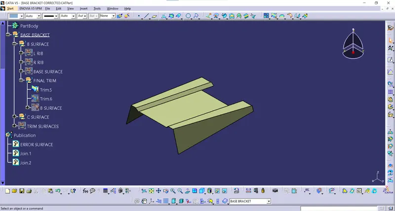
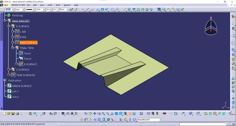
And then fillets are measured using the scale tool and then given accordingly
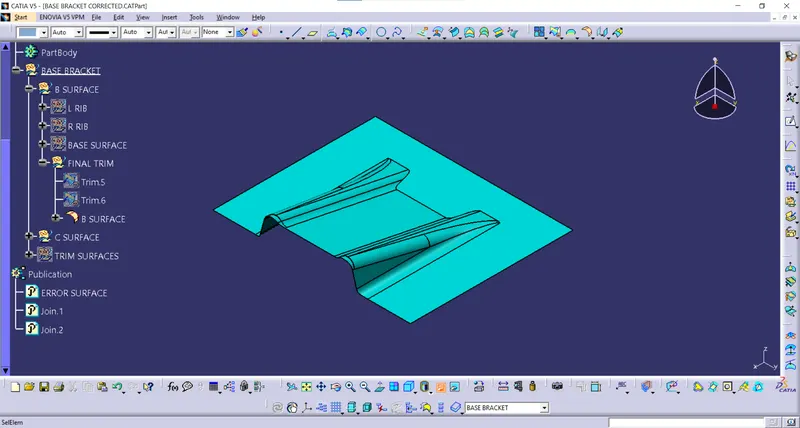
C SURFACE CREATION:
Initially, the boundary is being created for the class A surface profile
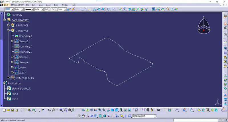
Then using the sweep command the boundary is swept below the class A surface to an arbitrart extent.
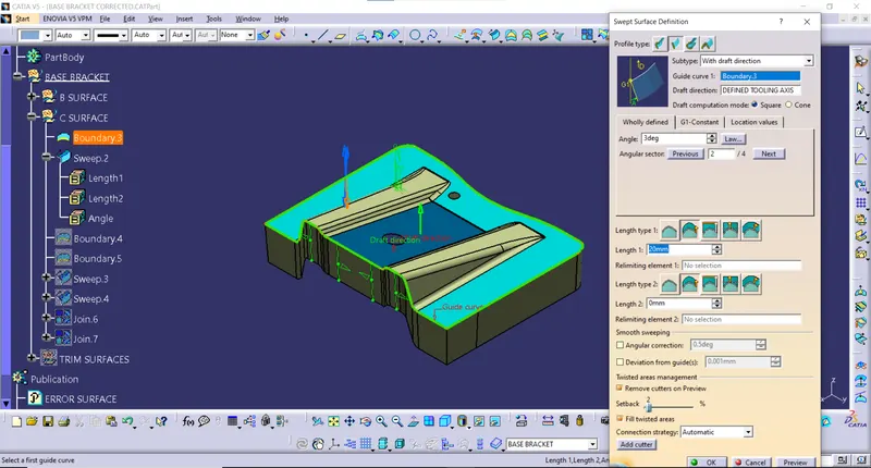
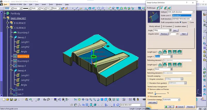
Then the circular hole profiles are swept the same method.
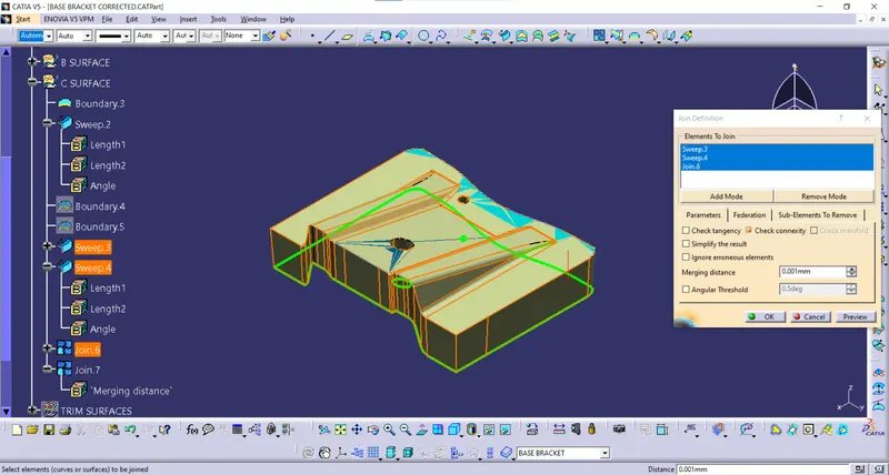
Then they are joined together completely to form a single entity.
Then the final trim between the A surface and the swept portion along with the length of B surface.
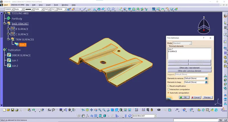
Then they are completed by giving the close surface command.