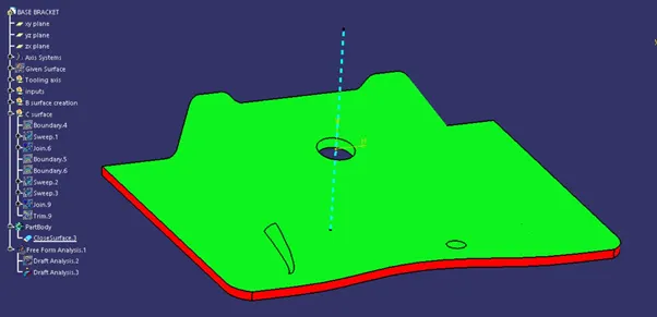
Week 8 - Challenge 2 - Base Bracket Design
In a (.IGS) File the class A surface come separately and not together. Hence, we need to join them together and then start performing the design. But the design has few error surfaces and we keep getting topological errors. To correct it we need to follow to following steps.
Tree structure:
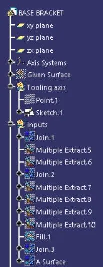
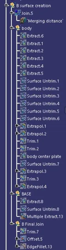
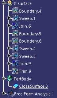
- Class A surface creation:
- Join 1: the class A surface excluding the error surfaces.
- Now extract the error surfaces using multiple extract.
- Multiple extract 1 is the upper surface.
- Multiple extract 2 is the bottom surface.
- Join 2: the multiple extract 2 with the class A Join 1.
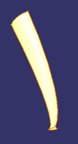
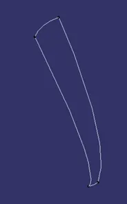
Error surfaces Extracted curves from multiple extract 1
- Now extract the curves of the multiple extract 1
- Now create a Fill with these Extracts to get a surface.
- Next join 3: Fill and join 2
- This join 3 becomes your class A surface
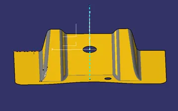
- Create tooling Axis
- create a sketch
- take an intersection of the component wall by clicking on the class A Surface Join.
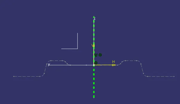
- This will give us an intersect of the component along Y-Z plane
- Draw two Lines that are tangent to the intersection line, and then draw a bisecting line with the two tangent lines as a selection and the axis point 1 as the reference.
- Then keep the bisecting line this becomes the tooling axis clearing direction, and make the other geometry as construction lines.
- B Surface Creation:
Create a Geometrical set and name it. Class B surface.
- Insert a geometrical set 1 with father as class b surface and name this set as Body
- Extract all the faces ignoring the fillet and the base surface from the class A surface.
- Un-trim the Extracts
- Extrapolate them
- Then trim them as per requirement.
- Insert a geometrical set with father as class b surface and name this set as BASE
- Extract the base
- Un-trim the base
- Extrapolate the base if needed
- Then trim the base with the body
Now we will have a complete Class B surface. we need to offset the surface for 2.5mm and then fillet the surfaces as per requirement
(In my project I was using a 3 mm fillet all around and adding the offset value to it
= 3+ 2.5)
Now we have a completed B surface.
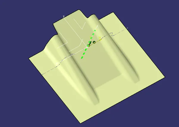
How To check fillet value:
- Extract a fillet
- Un-trim
- Then measure using measuring tool
Then Finally give the fillets for the class B surface. Make Sure to give proper dimensions because when you offset a surface you need to consider the fillet value to get Equal wall thickness.
Formula = thickness of the component – fillet radius.
- Creating Class C Surface:
- Take outer boundary of the class A surface.
- Use sweep command and sweep the boundary with lower inward projection with a draft angle of 3 degrees.
- Join the class A and class C surface. {JOIN 6}
- Use the boundary command again and extract the center holes separately and sweep the boundary for an angle of 4 degree.
- Now join this sweep with the join 6
- Finally trim the join with the b surface to get the final product.
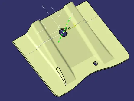
- Go to part workbench:
- Get the Closed surface of the profile into the Part-body.
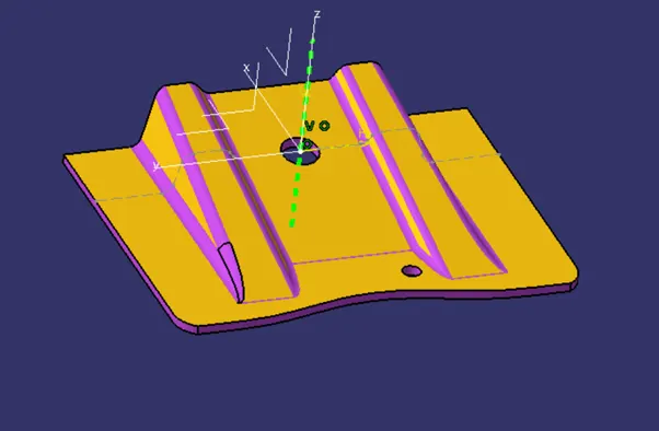
- Perform Draft Analysis:
- Go to customized view parameters and select on materials option and click ok.
- Then perform feature draft analysis
- Take the compass and fix it on the tooling axis, and the directions must be with respect to the original axis of the component.
- Lock the axis and check the color scale for the angle of draft.
- If it is constrained within maximum angle of draft = 3 degree, Then the component can be drafted.