Week 8 Challenge
We have modelled different types of power suppling devices like battery , fuel cell and from that one the Ultracapacitor model is been developed in this challenge. An ultracapacitor, also known as a supercapacitor, or electrochemical capacitor, is a device for storing electrical energy which is growing rapidly in popularity. The design and mechanism of operation is somewhere between an ordinary capacitor and a battery. Ultracapacitors store energy electrostatically, like a regular capacitor, not chemically like a battery. It can release it much quicker, as the discharge is not dependent on a chemical reaction taking place.
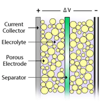
The ultracapacitor model looks as follows:-
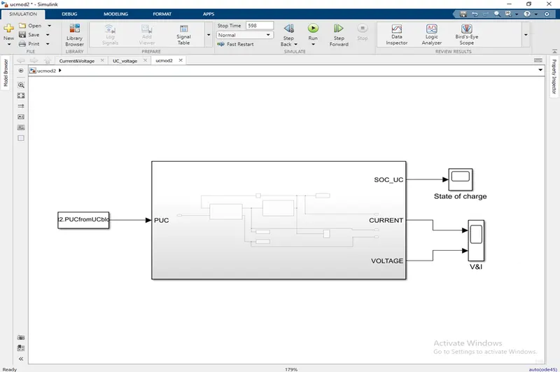
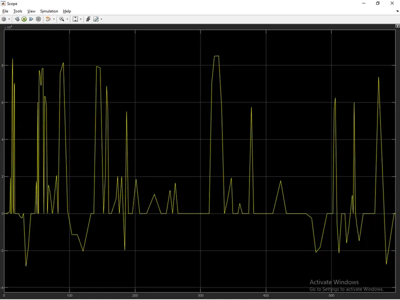
The power from the workspace is been taken by creating a array of power vs time as an input which is been supplied to the power control unit of the ultracapacitor model.
In Ultracapacitor model we have two more subsystem one for UC_current and one for calculating the SOC of the Ultracapacitor.
The inner model looks as follows :-
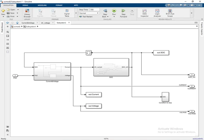
In this we are taking input as power input , first we will look into the model of UC SOC , the formula for calculating the SOC of UC is as shown below:-
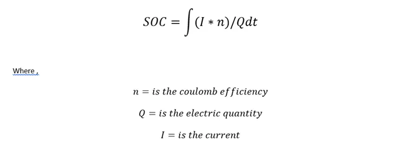
The current flowing through the circuit when integrated gives the charge flow through the circuit. Taking a ratio of it over total charge capacity gives SOC
Q depends on capacitance which is the charge storage capacity measured in farads.

C is the capacitance of the UC.
The open circuit voltage is a measure of the electric field between plates.

The capacitance and the OCV gives Q.
The integration of current over C hives OCV.
In the UC model , calculations for the current and SOC are done

R= is the lumped resistance
Vmax is the maximum voltage
n= is the efficiency during the charge discharge cycle.
As we have discused the formulas for calculating the SOC , current , charge and OCV we will be looking towards the implementation of this equations in matlab.
The SOC calculation subsystem is as shown below:-
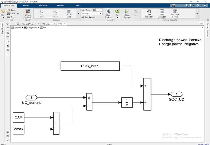
Here the current charge and efficiency are been given inputs to complete the values required necessary for estimating the SOC. From the Nominal SOC the resent or the present SOC is been subtracted and then taken as output.
For calculating the rest of the three parameters other subsystem is been created only for the simplicity of the model so that debugging of the model and studding the model will be easy.
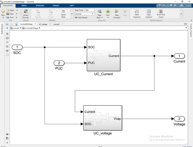
Again in this for each parameters a separate subsystem is been created as you can see in the above image.
We will be looking into the UC_Current subsystem , the model is as shown below:-
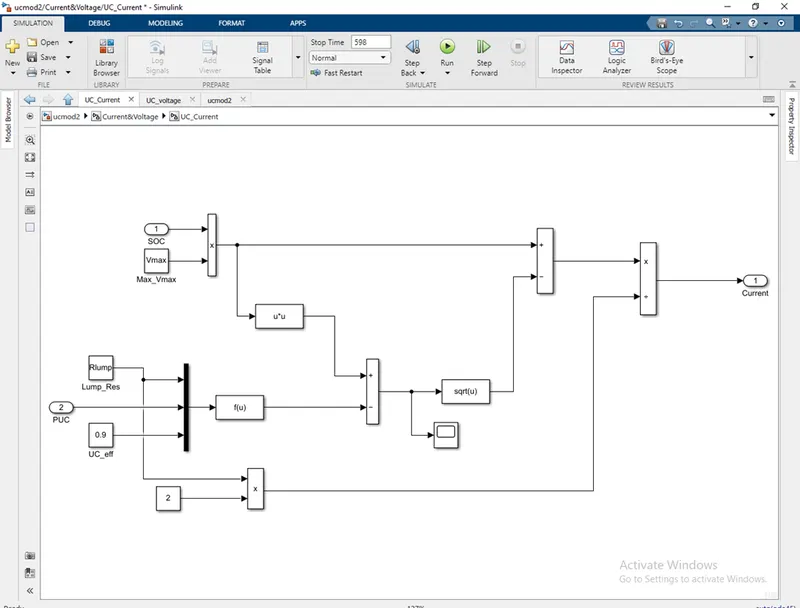
In this the UC max voltage , UC resistance and efficiency are been taken from the data sheet of the ultracapacitor. And as shown in formula the mathematical blocks are been used to implement in the equation.
Next step is to calculate the Open circuit voltage (OCV) , the Simulink model is as shown below:-
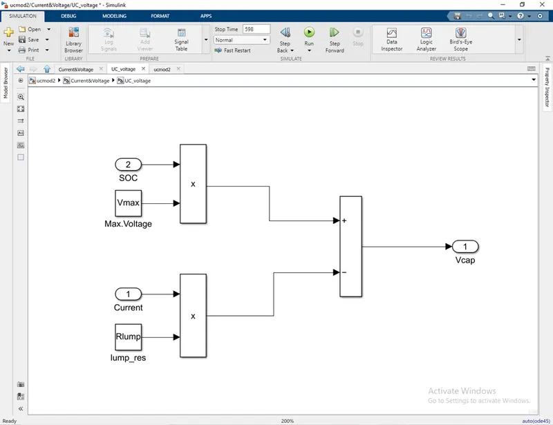
Even here the capacitance is taken from the data sheet.
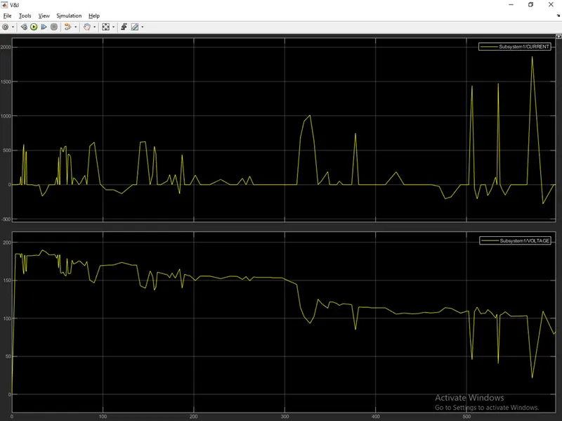
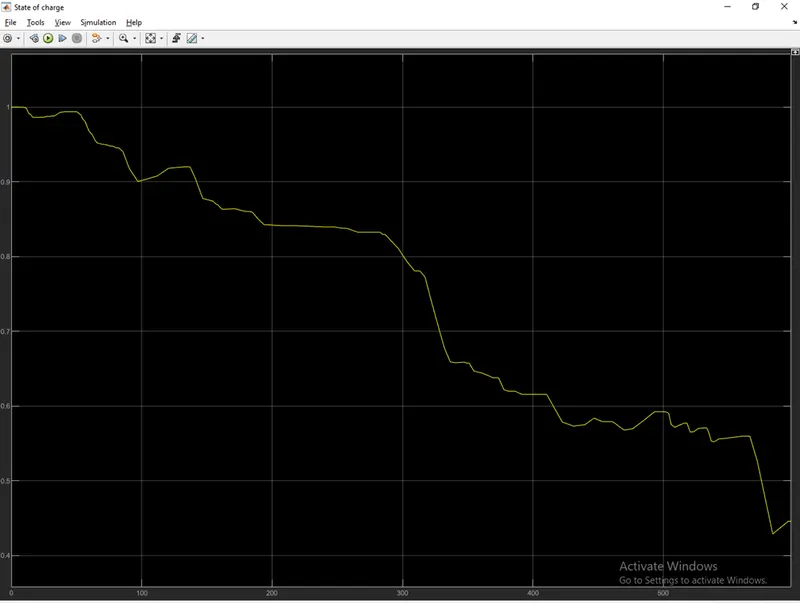
After crating or designing the Simulink model for all the parameters , we need to study them so the current , charge , voltage and SOC output are taken out of the model and connected to the scope , so from where we can have a clear look on the results.
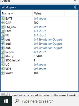
The constants which are been created are loaded into the workspace window and saved there.
The workspace window look as shown below:-
Results :-
Power demand as an Input Graph:-
SOC Scope:-
Voltage and Current Scope :-