Week -2
Challenge 2.1-
Doorbell
Aim- Make a Simulink model of Doorbell using solenoid block with the following details:
when the switch is closed the electromagnet receives electrical power from the battery and pulls the metal arm to
hit the bell producing sound.
Create a situation where the switch is closed for 2 seconds and then released. Observe the physical movement of the
plunger.
Solution-
For simulating the condition of a doorbell the blocks which are used are as follows -
1) Pulse Generator
2) Battery
3) Switch
4) Electrical reference
5) Solenoid Switch
6) Ideal Transalation Motion Sensor
7) Mechanical Reference
8) Solver Configuration
9) Simulink to Ps converter
Ps to Simulink Converter
10)Scope
This is the simulink model of doorbell -
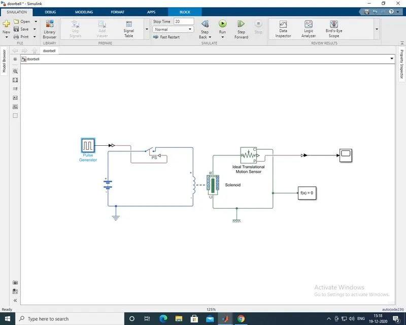
For making the basic transalation motion of ringing the bell I have used a solenoid switch, which will make a transalatary
motion and a ringing sound will be produced.
1) A battery is taken of 5V the positive terminal of battery is connected to the switch and from the switch its then
connected to the positive of solenoid and the negative of battery and solenoid is grounded to the electrical reference
block. A specified reference is always required to simulate the specific environment so the electrical reference block
is been used.
2) The Pulse Generator block is taken to provide the switching condition of 2sec so that it will supply current for
a specifie period of 2sec.For connecting this pulse generator to the switch a Simulink to PS converter block is used which
will enable the connection between this two.
3) A solenoid has 4 ports , 2 are elecrtical ports and the remaining 2 are mechanical poets the, two ports R & C are
representing the plunger in this the R port of plunger is moving away from port C of plunger , this are just motion direction
under excition.
4) For sensing the motion of the plunger an Ideal Translation motion sensor is used which will sense the translatery motion
of plunger.
5)Ideal Translation motion sensor has 4 ports , ports R & C are mechanical translation conversion ports and V & P are physical
signal output ports which will sense velocity and position respectively.
6) The R port of solenoid is connected to the R port of ideal translation motion sensor and the C port of plunger is
connected to the C port of ideal translation motion sensor and to this the mechanical reference block is been provided.
7) To solve this simulation we require one more additional block that is solver configuration , so I have used solver configuration
block and connected with the system.
8) The Modeling for this simulation is done almost now only the outputs are to be seen so the scope is been used but we cannot
connect the scope directly with the outputs of ideal translation motion sensor as its a PS block so before connecting this both
in between this the PS-simulink block is used, which will enable us to connect the scope.
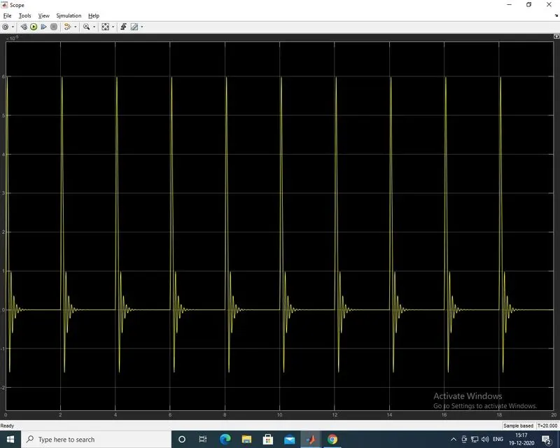
9) The results are been displayed in scope, the X-axis represents the time in seconds from 0-20 seconds and Y-axis represents
the position or the displacement of plunger. From the results its clear that the solenoid is switched on for 2sec.
Challenge 2.1
2. Use a thermistor to sense the temperature of a heater & turn on or turn off the fan as per below conditions:
Temperature source: 20 °C from 0 to 10 seconds, 27 °C from 10 to 30 seconds, 23 °C from 30 to 50 seconds
Fan conditions: ON if the temperature above 25 °C, OFF otherwise
In this Simulink model I have used specific blocks as follows-
1) Signal Biulder
2)simulink-PS converter
3)controlle Temperature source
4) Temperature reference
5) Thermistor
6) Current Sensor
7) Battery
8) Electrical Reference
9) Solver Configuration
10)Switch
11)Universal Motor
12)Ideal motion rotational sensor
13)Mechanical Reference
14)PS-simulink converter
15)Scope
This is the simulink model to sense the temperature of a heater & turn on or turn off the fan as per below conditions -
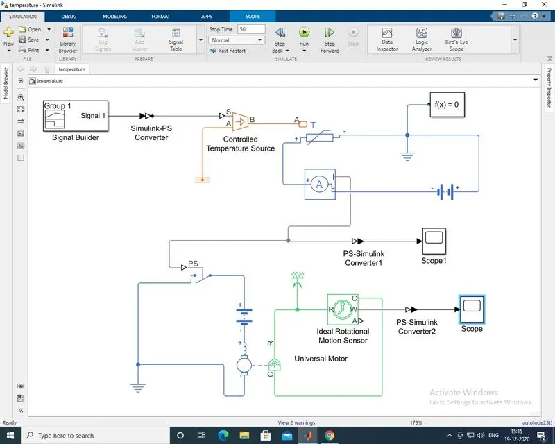
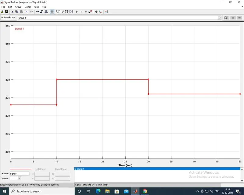
1)To build the initial condition of temperature with respect to time I have used signal builder block to specifi the conditions
in this I have set Time (sec) on X-axis and temperature (Kelvin) on Y-axis. As per mention in challenge from 0-10 sec the temperatur
is been set as 293 kelvin ,10-30 sec the temperatur is set 300 kelvin and from 30-50 sec the temperature is set as 296 kelvin .Now the conditions
has been set as per requirement.
This are signal builder parameters
2)Now the signals are taken out from signal builder block and given to controlled temperature source before connecting this two
blocks inbetween this simulink-Ps conveter block is used which enables to make a connection between this two. The controlled
temperature source is used to convert the signals of signal builder block into ideal thermal energy source, The temperature
difference is set by the physical signal port S. A positive temperature difference causes the temperature at port B to be
greater than the temperature at port A. Temperature reference is connected at port A of controlled temperature source. Its
necessary to use temperature reference for working of simulink model.
3) A thermistor is used, thermistor is nothing but an thermal resistor its simmilar to an electrical resistor. Thermistor has
three ports T is thermal port, + & - ports respectively they are Electrical conserving port associated with the thermistor
positive port and negative ports.
4) The negative of thermistor is connected to the positive of the battery and positive of thermistor is connected to current
sensor , the current sensor is used to sense the current and the nagative of current sensor is connected to the negative
terminal of battery, Now the circuit of thermistor is completed and a additional block of electrical reference is conneted to
work it successfully.
5) A solver configuration block is connected with the circuit of thermistor.
6) The output is taken from current sensor I port which is the output port, this is connected to scopr with the help of PS-simulink
converter.
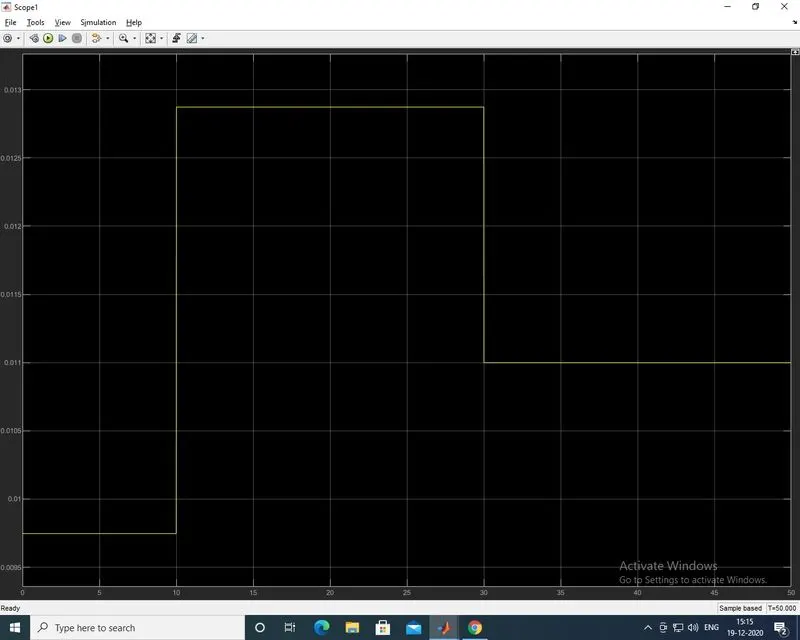
7)In the scope we are getting current of 0.0098 from 0-10sec which is near about 0 this means there is no current flow
in span between 0-10sec after this from 1-30sec the current is 0.0128 in this span the value of current is grater which means
there is flow of current in circuit in span of 10-30sec and at last in 30-50sec range the value of current is 0.011 which is low.
Results of current from I port of current sensor (scope 1)-
8) Now the next step in simulation is switching on & off of fan above 25 degree, so we have build the circuit for this with
the help of thermistor , now only we have to system for simulating condition of fan.
9) For this a Universal motor block is used and to sense the rotational motion an ideal rotation motion sensor block is used.
This rotational sensor has 4 ports R & C are mechanical rotational conversion ports , ports W and A are physical signal
output ports for velocity and angular displacement, respectively.
10)The output of current sensor is I is given to the switch in electric circuit of universal motor. The positive of universal
motor is connected to negative of battery and negative of universal motor is connected with the switch and then grounded with
electrical reference block.
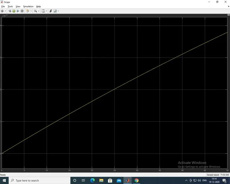
11) The output is taken from Ideal rotational motion sensor from W port to see the angular displacement of motor in rad/sec
its connected to scope with the help of PS-simulink block.
angular displacement/motion of universal motor(scope)-
In this way the simulation of a heater is been simulated in simulink environment.