Meshing of Housing Parts with 3D Tetra Elements using HYPERMESH
- Aim
To prepare housing parts for the finite element analysis, using solid elements.
- Objective
To discretize the housing parts into the finite number of solid elements for finite element analysis using pre-processor software viz. Hypermesh.
PROCEDURE
The STEP file of housing parts was imported in Hypermesh. There were 2 parts, one was the hub and the other was a disc, as shown in fig. 1, and fig. 2. They were not at all disturbed, and almost no errors were present in the geometry. However, the hub was present with only surfaces, and the disc was present with solid. Therefore, rather than the deletion of the solid of the disc, the two parts meshed with two different techniques. The disc was meshed as a solid, and the hub was meshed by converting 2d shell elements into 3d tetra elements.
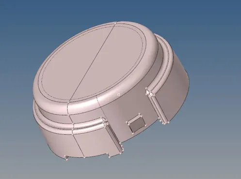
Figure 1: Hub of the housing assembly.
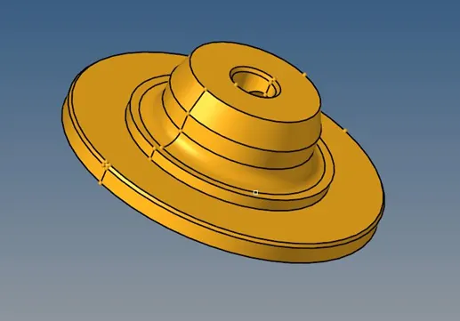
Figure 2: Disc of the housing assembly.
- Geometry Clean-up
The models imported were not having any significant errors, however, while performing 3d mesh, as a part of clean-up, the only thing which has to be cleaned are the shapes of geometry which fall below minimum element length criteria. If possible, it can be modified. Fig. 3(a) shows a similar case. In the hub model, the small step of 1.336, which was below 3 (minimum element length), was present. It was modified as shown in fig. 3(b).
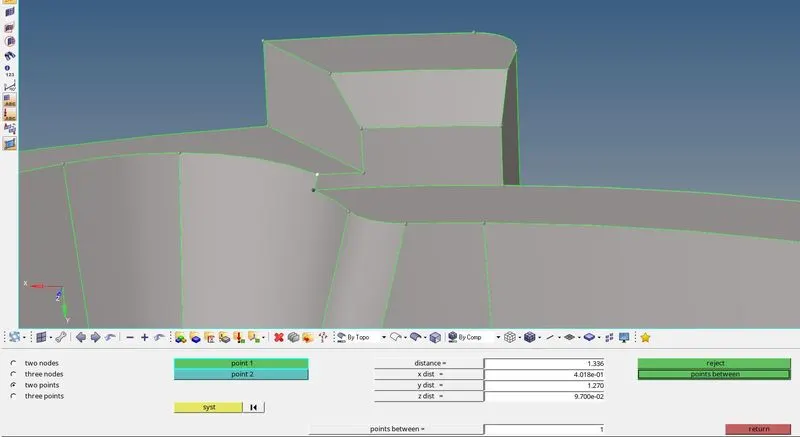
Figure 3(a): Small step of length 1.336.
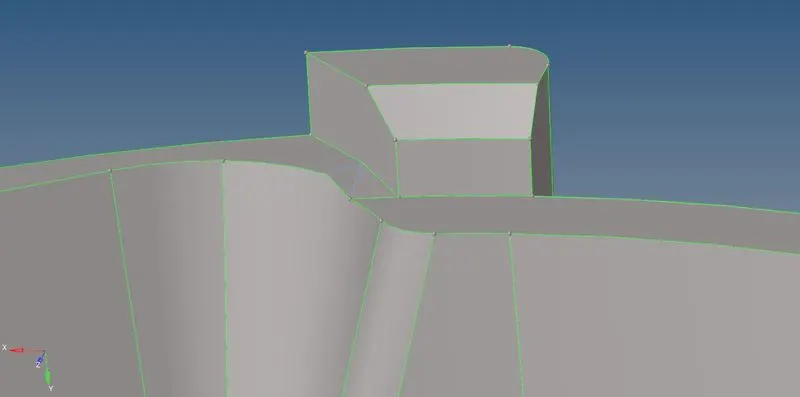
Figure 3(b): Modified small step. It was flattened.
- Setting Quality Criteria
For meshing these parts with solid elements four parameters were provided viz. minimum and maximum lengths, target length, and tetra collapse. The criteria provided for this model is as shown in table 1:
Table 1: Quality criteria for elements.
|
Target/Average length |
5 mm |
|
Minimum length |
3 mm |
|
Maximum length |
7mm |
|
Tetra Collapse |
0.15 |
- Meshing Solids with 3D Elements
Fig. 4 shows the solid of the disc. When the model is viewed in Topo mode, and if it appears like a green transparent structure, then it is a solid part. In 2d meshing, elements are deployed on the surface, thus, such solid is not required, and it is deleted. But, because in this work 3d elements have to be deployed, the solid was not deleted, and instead, it is meshed directly with 3d elements.
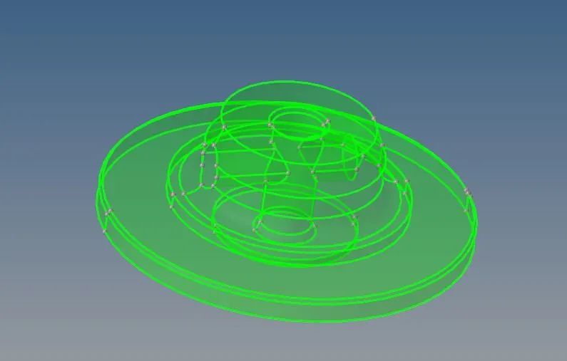
Figure 4: Solid of the disc.
To do that, there is an option, in 3D → tetramesh → Volume tetra, as shown in fig. 5. In that, the solid was selected, the element size was assigned as 5, the 2D type was tria, the 3D type was tetra, and the element order was the first order.
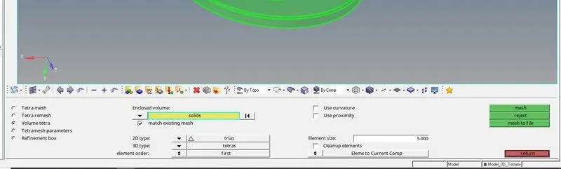
Figure 5: Volume tetra module.
After hitting mesh, the model was meshed perfectly, as shown in fig. 6.
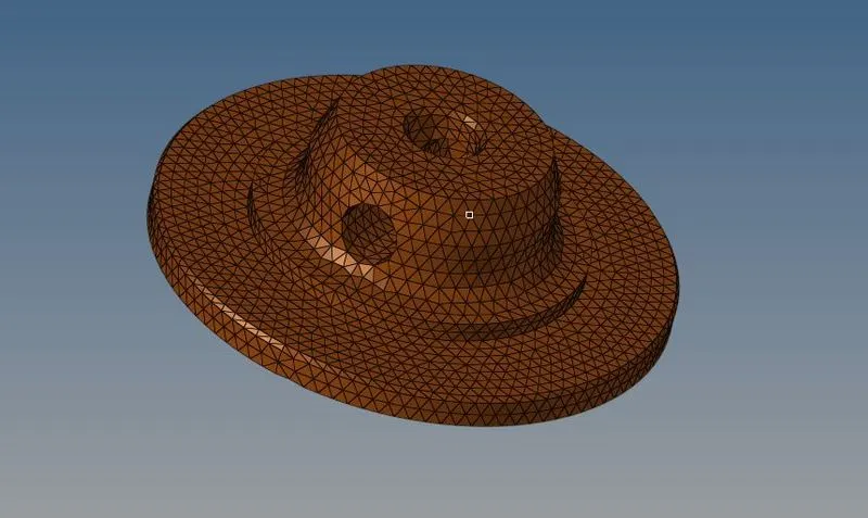
Fig. 6: Discretized disc using 3d tetra elements.
- Shell to Solid
The hub was not solid, and it was composed of surfaces. When viewed in the Topo mode, it appeared as shown in fig. 7.
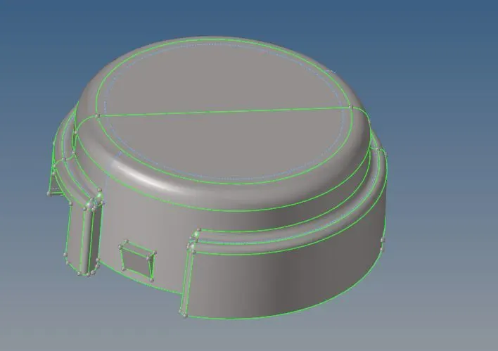
Figure 7: Hub model in the Topo mode.
When the model is composed of only surfaces, in such cases, it has to mesh with 2d elements, and then it has to be converted into 3d elements. Therefore, at first, using the ‘automesh’, the hub was meshed with 2d elements. Then using the 3D → tetramesh → Tetra mesh, selecting all the 2d elements, those 2d elements were converted to 3d tetra elements. Fig. 8 shows the discretized hub using 3d tetra elements.
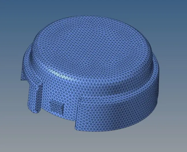
Figure 8: Discretized hub using 3d tetra elements.
- Quality Check
The only important thing that has to be checked in 3d meshing is the tet-collapse. To check the elements that failed for tet-collapse, the 'check elems' tool was used. Using the Tool → check elems → 3-d → tet collapse, it was found that 119 elements were failed for tet-collapse. To correct those elements, failed elements were saved, and using the 'mask' tool it was retrieved, masked, and then reversed masking. Doing that only failed elements were then visible as shown in fig. 9.
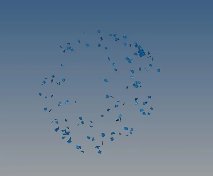
Figure 9: Elements failed for tet-collapse.
Now to correct the failed elements, there are two ways to do that. One is to adjust the length between nodes. It is a trial and error based method. And another method is to bring the adjacent elements (of failed elements) on to display, remesh the elements. Using both of the methods, all the failed elements were corrected, and the model was made free from failed elements.
CONCLUSION
Objects whose thickness is not regular or if it is above 5-6 mm, generally meshed with solid elements. Generally, when the developing stresses in any object are not the part of the concern, it is meshed using tetra elements. Else, it has to be meshed with 3d Hexa elements. If the object is a critical part, it has to be meshed with Hexa elements.
PRE-PROCESSING ON CRANK HOUSING OF AN AIRCRAFT ENGINE
- Aim
To prepare the crank housing of an aircraft engine for the finite element analysis, using solid elements.
- Objective
To discretize the crank housing of an aircraft engine into the finite number of solid elements for finite element analysis using pre-processor software viz. Hypermesh.
PROCEDURE
The .hm file of crank housing was imported in Hypermesh. The housing was a single part as shown in fig. 1. It was having almost no errors in the geometry. However, the housing was present with only surfaces. Therefore, the housing was meshed by converting 2d shell elements into 3d tetra elements.
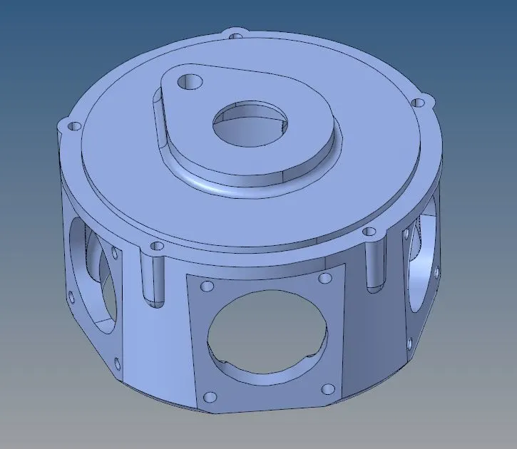
Figure 1: Crank housing of an aircraft engine.
- Geometry Clean-up
The models imported were not having any significant errors, however, while performing 3d mesh, as a part of clean-up, the only thing which has to be cleaned are the shapes of geometry which fall below minimum element length criteria. If possible, it can be modified. However, in the housing, no such allowable modification can be done.
- Setting Quality Criteria
For meshing the housing parts with solid elements two parameters were provided viz. target length, and tet collapse. The criteria provided for this model is as shown in table 1:
Table 1: Quality criteria for elements.
|
Target/Average length |
6 mm |
|
Tetra Collapse |
0.15 |
- Shell to Solid
The housing was not solid, and it was composed of surfaces only. When viewed in the Topo mode, it appeared as shown in fig. 2.
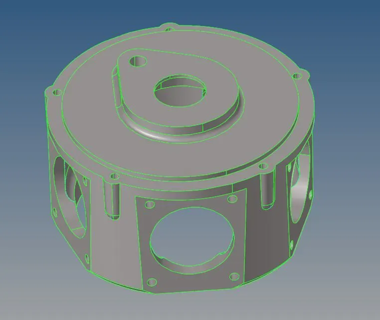
Figure 2: Crank housing of an aircraft engine in the Topo mode.
When the model is composed of only surfaces, in such cases, it has to mesh with 2d elements, and then it has to be converted into 3d elements. Therefore, at first, using the ‘automesh’, the hub was meshed with 2d elements. Then using the 3D → tetramesh → Tetra mesh, selecting all the 2d elements, those 2d elements were converted to 3d tetra elements. Fig. 3 shows the discretized hub using 3d tetra elements.
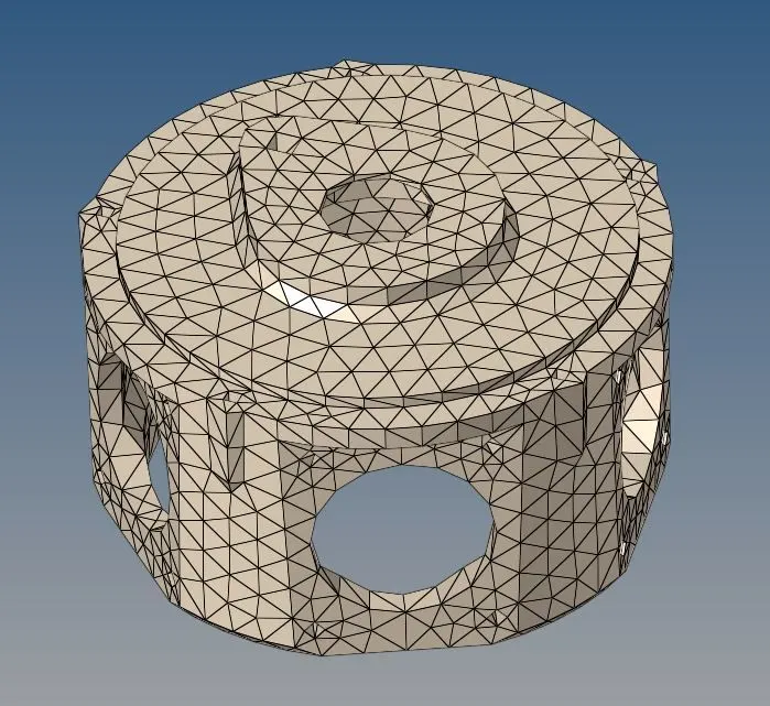
Figure 3: Discretized housing using 3d tetra elements.
- Quality Check
The only important thing that has to be checked in 3d meshing is the tet-collapse. However, in this model, no were elements failed tet-collapse.
CONCLUSION
Objects whose thickness is not regular or if it is above 5-6 mm, generally meshed with solid elements. Generally, when the developing stresses in any object are not the part of the concern, it is meshed using tetra elements. Else, it has to be meshed with 3d Hexa elements. If the object is a critical part, it has to be meshed with Hexa elements.
PRE-PROCESSING ON PARTS OF WHEEL ASSEMBLY
- Aim
To prepare the parts of wheel assembly for the finite element analysis, using solid elements.
- Objective
To discretize the parts of wheel assembly into the finite number of solid elements for finite element analysis using pre-processor software viz. Hypermesh.
PROCEDURE
The .igs file for the parts of wheel assembly was imported in Hypermesh. The assembly composed of four parts as shown below figures. It was having almost no errors in the geometry. All the parts were composed of surfaces only, and no solids. Therefore, parts were meshed by converting 2d shell elements into 3d tetra elements.
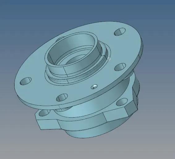
Figure 1: The wheel hub.
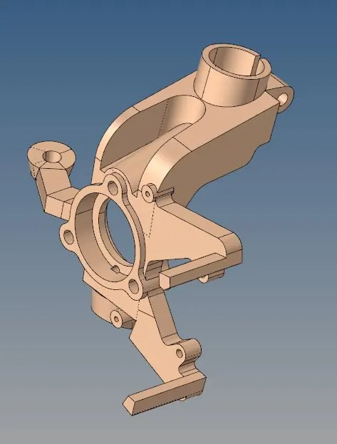
Figure 2: The knuckle.
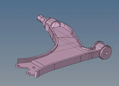
Figure 3: The lower control arm.
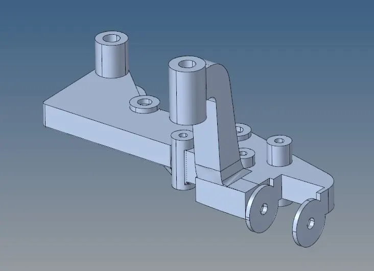
Figure 4: The frame part.
- Geometry Clean-up
The models imported were not having any significant errors, however, while performing 3d mesh, as a part of clean-up, the only thing which has to be cleaned are the shapes of geometry which fall below minimum element length criteria. If possible, it can be modified. Moreover, some lines which were not required were suppressed.
- Setting Quality Criteria
For meshing the housing parts with solid elements two parameters were provided viz. target length, and tet collapse. The criteria provided for this model is as shown in table 1:
Table 1: Quality criteria for elements.
|
Target/Average length |
6 mm |
|
Tetra Collapse |
0.15 |
- Shell to Solid
The housing was not solid, and it was composed of surfaces only. When the model is composed of only surfaces, in such cases, it has to mesh with 2d elements, and then it has to be converted into 3d elements. Therefore, at first, using the ‘automesh’, the hub was meshed with 2d elements. Then using the 3D → tetramesh → Tetra mesh, selecting all the 2d elements, those 2d elements were converted to 3d tetra elements. Fig. 5 shows the discretized wheel assembly, using 3d tetra elements.
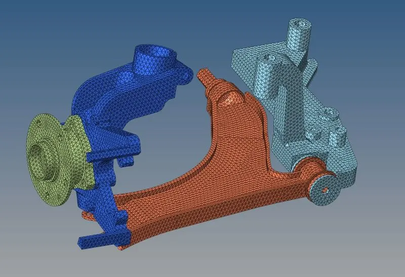
Figure 5: Discretized housing using 3d tetra elements.
- Quality Check
The only important thing that has to be checked in 3d meshing is the tet-collapse. However, in this model, no elements were failed for tet-collapse.
CONCLUSION
Objects whose thickness is not regular or if it is above 5-6 mm, generally meshed with solid elements. Generally, when the developing stresses in any object are not the part of the concern, it is meshed using tetra elements. Else, it has to be meshed with 3d Hexa elements. If the object is a critical part, it has to be meshed with Hexa elements.