Week 8 Challenge (A simulink model for ultracapacitor of EV, input as power demand request from EMS and output as UC voltage, UC current, UC SOC)
CHALLENGE 8
Objective:
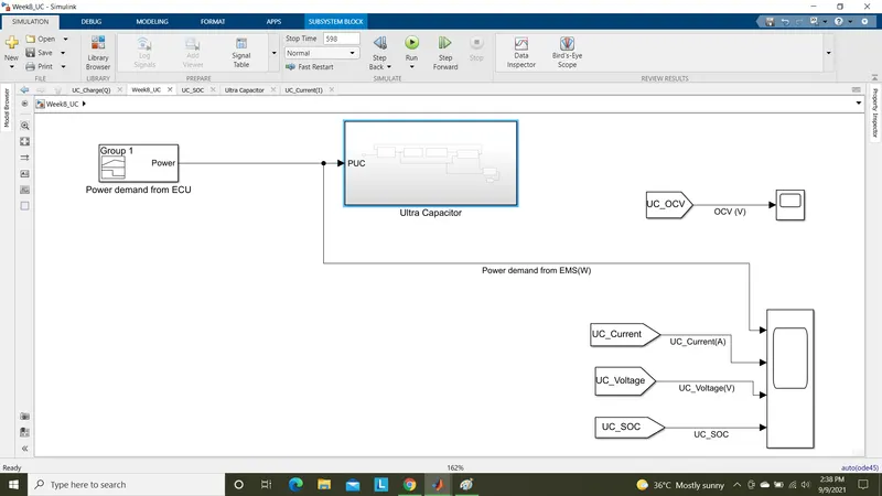
To create a simulink model for a ultra capacitor of a electric vehicle, in which input for ultracapacitor is the power demand(PUC) from Energy Management System(EMS) and outputs as,
- Ultracapacitor voltage.
- Ultracapacitor current.
- Ultrcapacitor SOC.
Ultracapacitors:
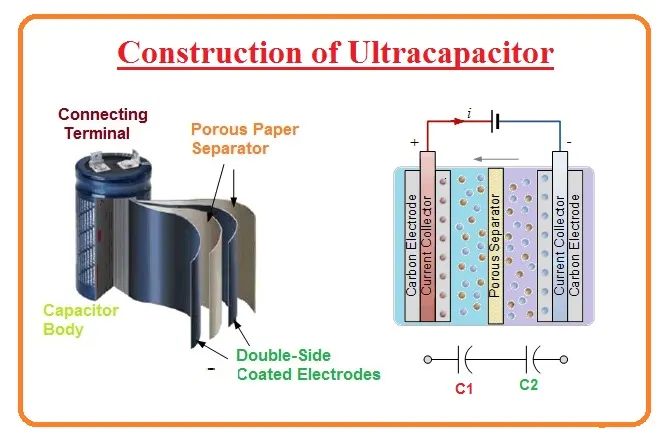
An ultracapacitor also known as a supercapacitor or electrochemical capacitor is a device for storing electrical energy which is growing rapidly in popularity.
The design and mechanism of operation is somewhere between an ordinary capacitor and a battery, which opens up some interesting and valuable applications.
Like a battery a single ultracapacitor cell consists of a positive and negative electrode, separated by an electrolyte. However ultracapacitors store energy electrostatically like a regular capacitor, not chemically like a battery.
There is a dielectric separator dividing the electrolyte also like a capacitor.The small separation between electrodes permitted by this structure lead to much higher energy storage density than a normal capacitor.
Ultracapacitors stores less energy than an equivalently sized battery.It can release it much quicker, as the discharge is not dependent on a chemical reaction taking place.
Because no physical or chemical changes occur when charge is stored, ultracapacitors can also be used many times over without degradation.
Instead of single layer anode and cathode electrodes a double layer electrode ultra capacitors are used as it increases the capacitance due to larger electrode areas.
Applications of Ultracapacitors:
- Electric or Hybrid vehicles.
- Quick charging electronic devices.
- Water proof energy storsge devices(e.g Remort wind farms)
- Military vehicles(Starter engines for tanks, submarines, compact power for missiles).
Advantages of Ultacapacitors:
- Long life time(1+million charge cycles)
- Maintenance free and reliable.
- Near full efficiency even in extreme temperatures, from -40 °C to 65 °C.
- Up to 60 times the power density achieved by batteries.
- 30% more efficient than batteries.
Ultracapacitor parameters:
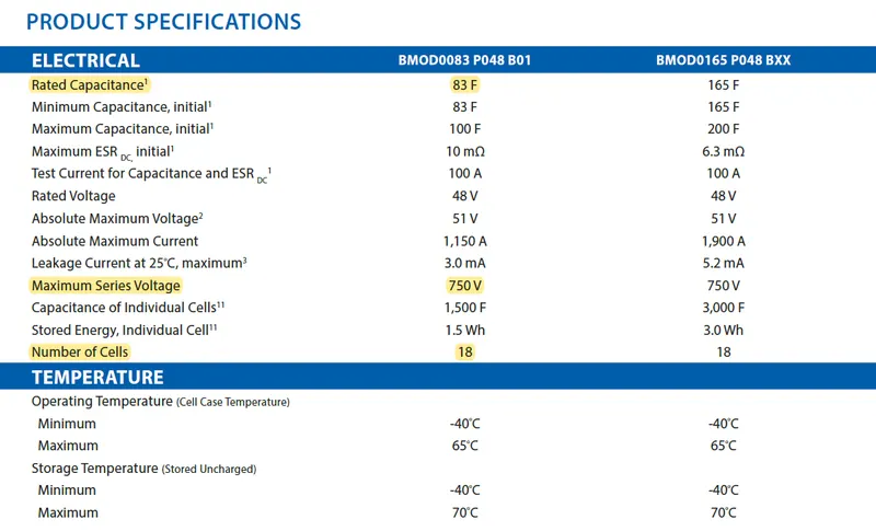
Lets take a Ultracapacitor model BMOD0083P048B01 from the make of Maxwell Technologies.
Its data sheet specification of parameters to model our ultracapacitor are shown from its datasheet as below,
Overall Model of Ultracpacitor:
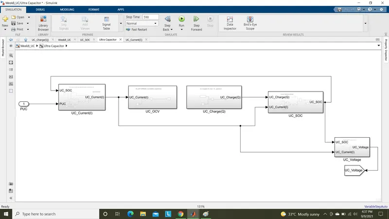
The Ultacapacitor subsystem consist of five subsystems as shown below,
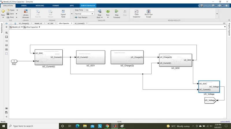
From these block we can get the outputs as,
- Current drawn(Discharging) and Current passing(Charging) through ultracapacitor-(UC_Current subsystem).
- Open circuit voltage at overall simulation time-(UC_OCV subsystem).
- Charge drawn(Discharge) and charge passing(Charging) through the ultracapacitor-(UC_Charge subsystem).
- SOC of ultracapacitor on overall simulation time-(UC_SOC subsystem).
- Ultracapacitor voltages on overall simulation time-(UC_Voltage subsystem).
Construction of subsystems:
1) UC_SOC subsystem:
From this block we can get the results of SOC's of ultracapacitor through overall simulation time of 598secs corresponding to the power demand from EMS.
The inputs for this subsystem are ultracapacitor current(UC_Current),ultra capacitor efficiency(UC_Eff),ultracapacitor charge(UC_Charge).
The output is SOC of ultracapacitor.
This output SOC is subtracted from nominal SOC value of ultracapacitor as it should tries to get maintained at every period of vehicle running.
Here we are taking initial SOC of ultracapacitor as 90% to see the SOC increase and decrease from this state of charge.Thus SOC from relation is subtracted from Initial SOC of ultracapacitor.
The SOC of ultracapacitor be given by the relation,
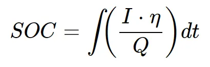
This equation is implemented as mentioned below,
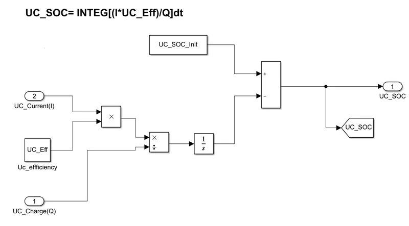
The UC_Current and UC_Charge inputs are given from respected subsystems.
2) UC_Charge Subsystem:
From this block we can get the Charge drawn and supplied to the ultracapacitor corresponding to the power demand from EMS.
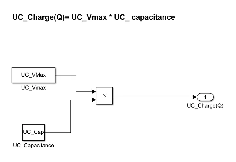
The UC_Charge can be estimated by multiplying the Maximum voltage and Capacitance of ultracapacitor.
These values are assigned in workspace.
This can be given in relation by,

This relation is implemented in this subsystem as shown below,
3) UC_OCV subsystem:
From this block we get the open circuit voltages of ultracapacitor over the simulation time of 598 secs.
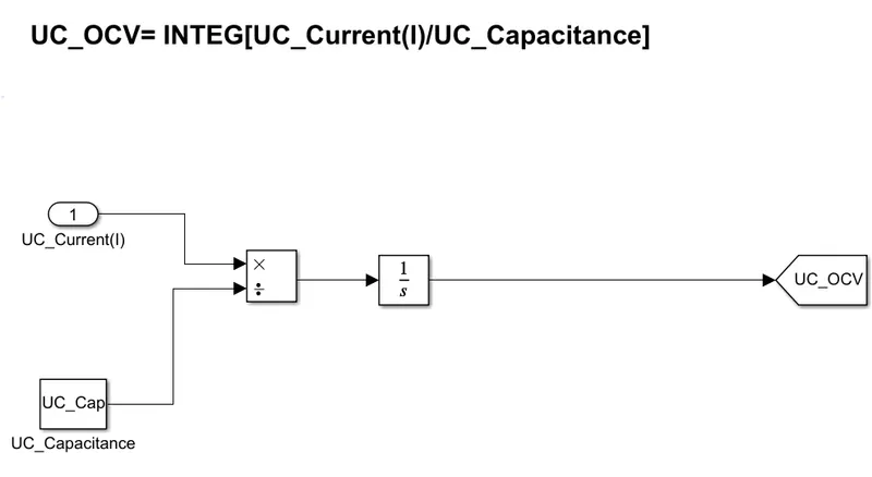
The input of this subsystem is ultracapacitor current divided by capacitance value and gets integrated over the time to get the output open circuit voltage.
This can be given in relation as,
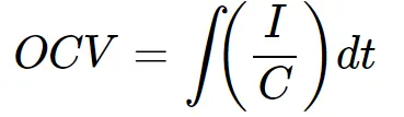
This relation was implemented in this subsystem as shown below,
4) UC_Current subsystem:
From this subsystem we can get the ultracapacitor current output which can fed as input to UC_SOC,UC_OCV and UC_Voltage subsystems to find the state of charge,open circuit voltage and ultracapacitor voltages respectively for upto the end of simulation period.
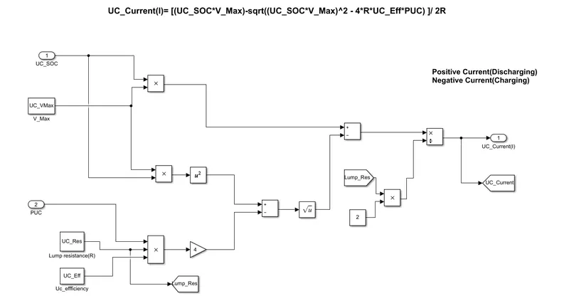
This subsystem inputs are UC_SOC,ultracapacitor maximum voltage value,UC lump resistance value,ultrcapacitor efficiency and finally the power demand(PUC) from Energy Management System(EMS) unit.
The ultrracapacitor current is estimated from the relation as given below,
`I=((SOC*Vmax)-sqrt[(SOC*Vmax)^2-(4R*eta*PUC)])/(2R)`
This relation was implemented in this subsystem as shown below,
5) UC_Voltage subsystem:
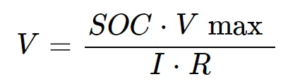
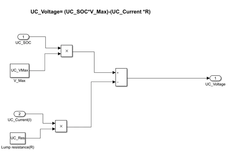
From this subsystem we can get the voltage values of ultracapacitor corresponding to the power demand for overall simulation time.
This can be given as in relation,
This relation was implemented in this subsystem as shown below,
Parameters for the model:
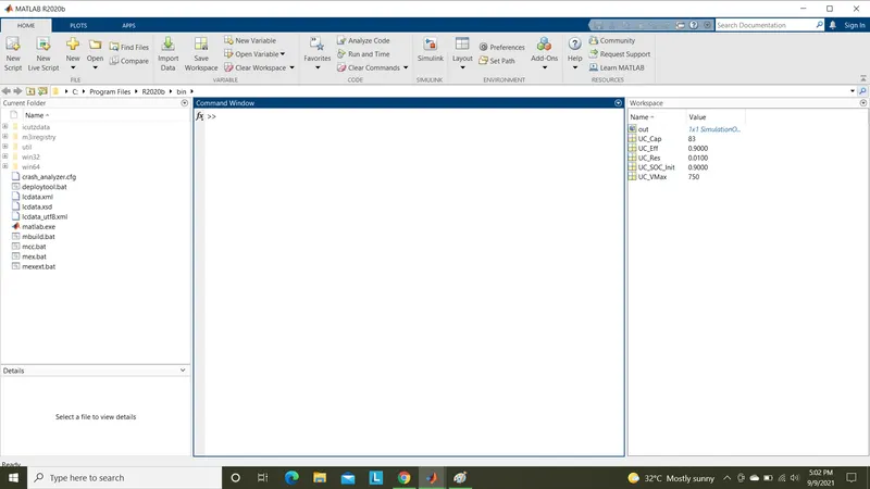
The inputs given for model subsystems from base workspace are,
- Capacitance of ultracapacitor: UC_Cap=83F
- Ultracapacitor charge efficiency: UC_Eff=0.9 as 90%.
- Lump resistance of ultracapacitor: UC_Res=0.01
- Initial SOC of ultracapacitor: UC_SOC_Init=0.9 as 90%.
- Maximum voltage of ultracapacitor stack: UC_Vmax=750 V.
These parameter values are referred from the datasheet as mention initially and loaded to a .mat file which is attached with this challenge submit.
The assigned values in base workspace as shown below,
Working of model:
Step 1:
Initially the power demand(PUC) from EMS unit is given to the ultracapacitor subsystem block.
For simplicity we can give this power demand input from a signal builder block.
The power demand datas with respect to time (598 secs) from an excel file is imported into the signal builder block as shown below,
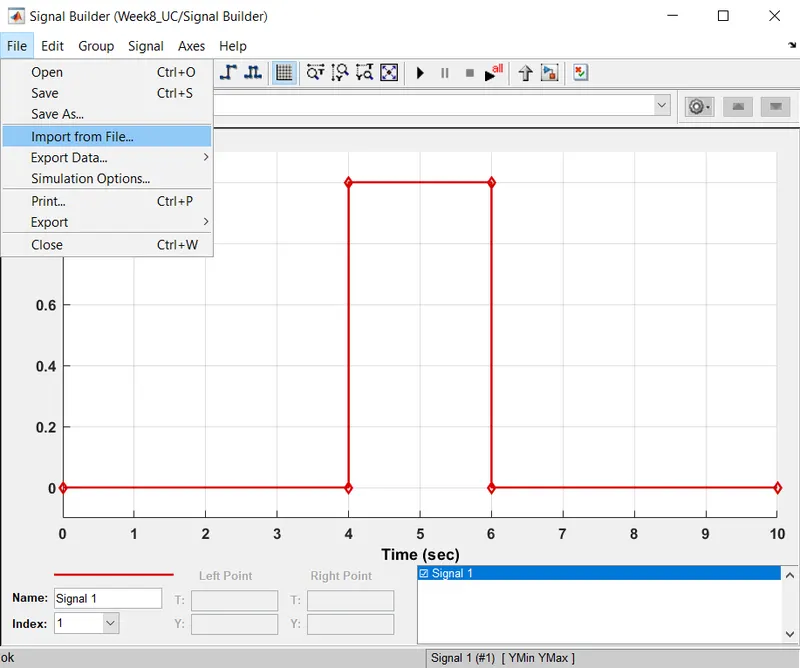
Select import file from file menu.
A dialog box opens to select the file to import into signal builder block.
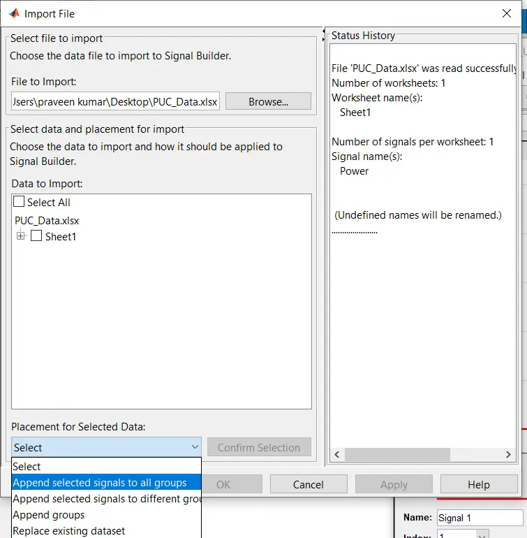
Choose the excel data from browse option and then check select all check box, then give Append selected signals to all groups from placement for selected data.
Then click apply and ok.
We get the power demand signal as shown below,
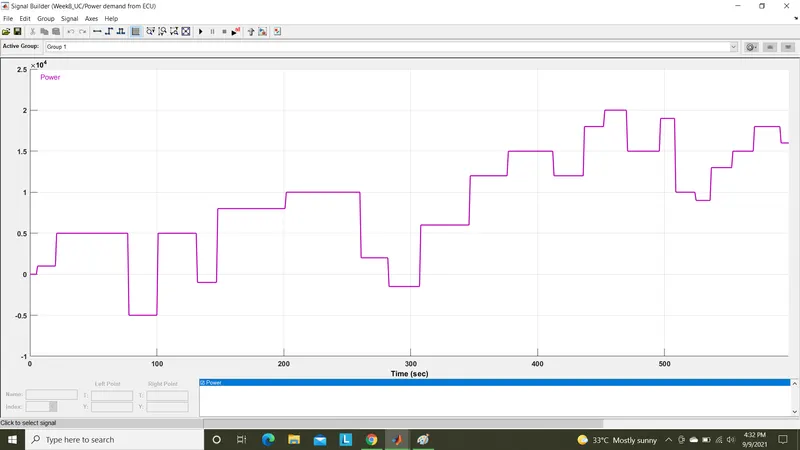
Here the Positive power values represents the discharging power demand and Negative power values represents the ultacapacitor charging.
Step 2:
This power demand signal is given as input for Ultracapacitor subsystem.
Inside this subsystem another five subsystems as discussed earlier are get computed by this power demand signal.
This can be shown as,
Step 3:
The PUC signal and SOC of ultracapacitor from UC_SOC subsystem as feed back given as inputs to UC_Current subsystem.
The output from this block is UC_current values.
The computation of this current values is discussed earlier in construction of subsystems part.
Step 4:
The output UC_Current is given as input to UC_OCV subsystem.
From this subsystem we can get the open circuit voltage values for the overall simulation period.
Step 5:
The ultracapacitor charge UC_Charge(Q) value calculated from UC_Charge subsystem is gien as input to UC_SOC subsystem along with UC_Current values input.
From this we get the SOC of ultracapacitor as UC_SOC. This signal values are again gieven as feedback to UC_Current subsystem block as we seen in step 3.
This process loop continues untile the simulation stop time reach.
Step 6:
The UC_Current and UC_SOC, values are given as inputs to UC_Voltage subsystem.
From this we can get the ultracapacitor voltage drop and rise values.
Results:
Run the simulation for 598 seconds and the results we get for the given power demand input signal are as shown below,
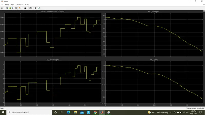
- The first plot shows the Power demand as input signal.
- The second plot shows the UC_Voltage drop and increase correspond to power demand.
- The third plot shows the UC_Current output of ultracapacitor.
- The Forth plot displays the SOC of ultra capacitor.
From these plots we can understand that,
The Current drawn from ultracapacitor and supplied into ultracapacitors are followed correspond to the power demand.The maximum current discharge is shown as nearly 27 Amps and maximum current supplied into the ultra capacitor is nearly 6.5 Amps as shown in above UC_Current plot.
The voltage initially starts at nearly 675 V and at end of the simulation the voltage output as 594 V.At the time duration of 77 secs to 102 secs the ultracapacitor is in charging mode.At that time the voltage gets rised somewhat as shown below.
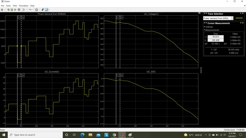
The SOC of ultra capacitor varies corresponding to the voltage as ultracapacitor voltage is directly proportional to SOC of ultracapacitor.The SOC is rised up during the charging period as shown in above plot.
The SOC of ultracapacitor starts at 90% as we mentioned and decreased to nearly 79% for overall simulation duration of 598 secs.
Conclusion:
From this plots it is clearly understand that the ultracapacitors can be used in high power required in short duration of time.
As power demand increases suddenly,the current drawn from ultracapacitor also increases drastically correspond to power demand.
This justifies that ultracapacitors are having high specific power.
This can't be acheived from batteries as they have lesser specific power when compared to ultracapacitors.
Note: The model file,Workspace .mat file and Excel file are attached with this submission.
Submitted by,
Praveen Kumar L V.
Date:9/9/2021.