Project(Case study of BAJA ATV(All Terrain Vehicle) Model using CVT(Continuously Variable Transmission).
PROJECT
Case study of BAJA ATV(All Terrain Vehicle) Model using CVT(Continuously Variable Transmission)
Summary:
In this model we are analysing various parameters of a BAJA vehicle in different situations.The main motive for creating this model to analyse the result outcomes like velocity of the vehicle,range of the vehicle,engine rpm at initial stage,CVT's primary and secondary pullies rpm by changing various configurations of the vehicle parts like engine parameters using torque speed characteristics,gear ratio's,CVT ratios
using signal builders,look up tables.
We have different cases varies according to CVT arrangements,
Case 1: cvtModel-Contains simscape model of BAJA ATV with continuous variable transmission.
Case 2: cvtModel_dashboard-This model is same as Case 1 along with addition of dashboard.
Then using lookup tables,
Case 3: cvtModel_cvtratio_rpm-This model build with cvt ratio and engine rpm lookup table.
Case 4: cvtModel_mapped- In this model cvt ratio varies based on PS-1D lookup table.
Case 5: cvtModel_dashboard_mapped- This model is similar to case 4 added with dashboard.
Case 6 :cvtModel_data - This model is used to log the cvt ratio and vehicle speed for the look table visualization.
Case 7 : lookuptable_visualization-Script to load and run the model,cvtModel_data.
Prducts required:
Matlab version from R2018b release, 1)Matlab 2)Simulink 3)Simscape 4)Simscape driveline.
Blocks used:
- Signal builder: For Throttle input,brake input,CVT ratio simulink signal builder.
- Generic Engine,Mechanical Rot.Referance.
- Ideal rotational motion sensor:For engine rpm senceing,CVT primary and secondary rpm senceing.
- Variable ratio transmission: As cvt.
- Inertia: For input and output shaft of Cvt and in vehicle axle gears.
- Simple gear:For CVT to vehicle axle tansmission.
- 1D Lookup table-For CVT ratio input with engine rpm.
- PS lookup table- For CVT ratio input with with velocity feedback from vehicle.
- Vehicle body,Tire,Integrator,PS terminator,Double shoe break,gain block,PS constant,Rotational free end.
- From,Goto,PMC Connector,Scope.
Working:
- Initially the throttle input given as a signal to engine by coverting to physical signal.The engine speed and torque are assigned from the data from base workspace data table.That shown in image file link in model.
- The speed of engine in rpm is senced using ideal rotational motion sencor,display in scope.This engine output given to CVT primary shaft as input and get output from follower as secondary shaft.
- According to CVT ratio's given to primary as physical signal between certain time intervals continuously the speed of secondary shaft varies accordingly.
- The speed of prmary and secondary shafts are senced instantaniously by using ideal rotational motion sencors.Here added the input and output shaft inertia of the gears that are assigned as variables from base workspace(m1 and m2).
- The secondary shaft output given as base to external gear of standard gear ratio 10.Then its follower output given as input to wheel axle A ports of vehicle wheel . Here comes brake input given to double shoe brake as mechanical brake connected with wheel.
Here shows the snap of vehicle body,
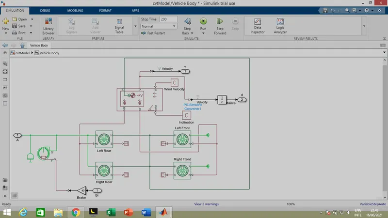
The wind velocity and hill climbing parameters are given as input at bete and w input ports.The physical force signals of stering are given to N port of wheel as input. V is the output port for velocity of vehicle visible through scope.The velocity values get integrated to get the value of range covered by the vehicle. These are the working of the model.
Now we can see the diferent cases of cvt ratio input methods and analyse the results.
Case 1: cvtModel-Contains simscape model of BAJA ATV with continuous variable transmission.
Here Cvt ratio inputs given with signal builder inputs.Throttle and break are given as signal builder inputs.
Model:
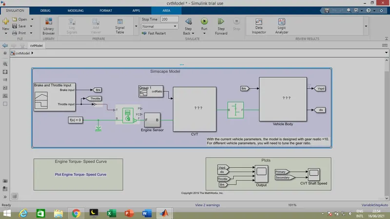
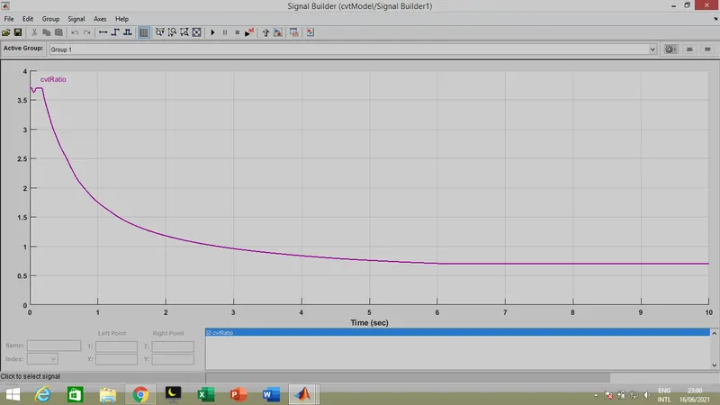
Here throttle input is 0.5 and brake input is 0 initially. Cvt ratio inputs are acheived using cvt ratio .mat file.
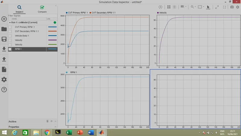
Result:
While running the model we get the outputs,depending upon the CVT ratio decreasing the secondary shaft speed increasing due to which velocity of body increasing exponentialy with standard gear ratio 10.The rpm of engine and primary cvt shaft are equal as they are directly coupled.
Case 2: cvtModel_dashboard-This model is same as Case 1 along with addition of dashboard.
Here same as the case 1 parameters but additionally daseboard is attached for visible of output and giving input.
Model:
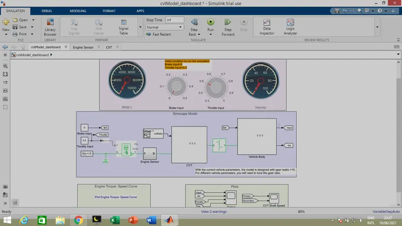
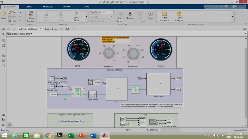
Throttle and break inputs are given in knobs present in dashboard.The output velocity and engine rpm are visible in speedometer accordingly while change knob inputs.
Result:
While running the model we can see changes in dashboard.The engine rpm is nearly 3400 and velocity is nearly 50 at that instant.
Case 3: cvtModel_cvtratio_rpm-This model build with cvt ratio and engine rpm lookup table.
Here cvt ratio is given through 1D lookup table where speed and cvt ratio datas are feeded from Lt_cvtratio_rpm .mat file.
Model:
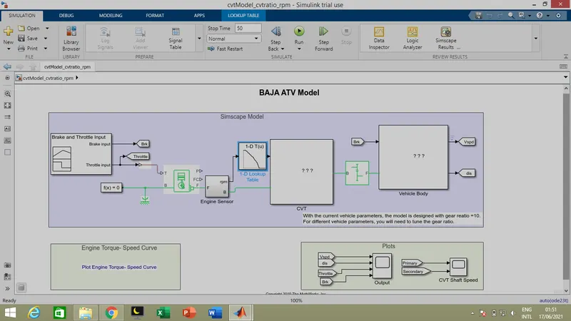
Throttle and break input are given through signal builder.
Result:
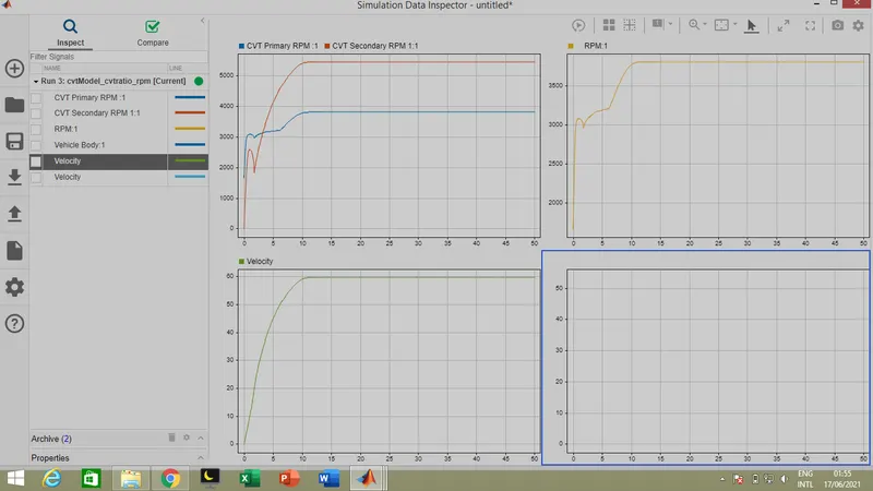
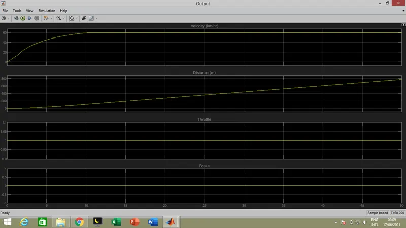
The primary cvt shaft and engine rpm are closely same.cvt secondary rpm increases and decreases corresponding to its cvt ratio.
Distance covered:
Distance covered is around 780 m.
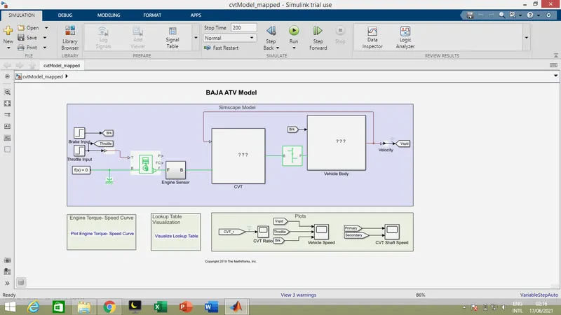
Case 4: cvtModel_mapped- In this model cvt ratio varies based on PS-1D lookup table.
Here for cvt ratio look up table is used and speed get as a feedback from velocity of vehicle.
Model:
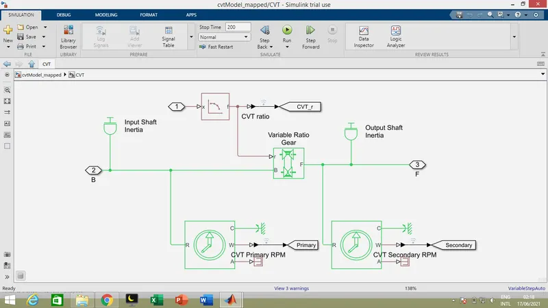
CVT:
Here the cvt ratio assigned from Lookuptable_data .mat file.
Result:
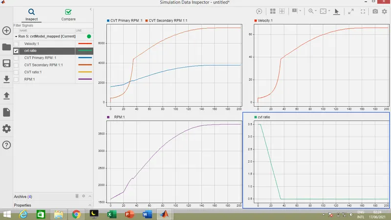
From the results we can compare the parameters according to the cvt ratio.
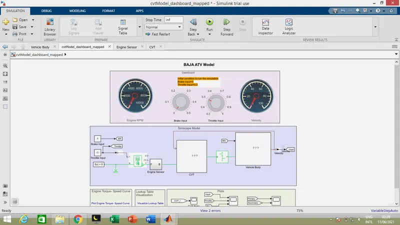
Case 5: cvtModel_dashboard_mapped- This model is similar to case 4 added with dashboard.
Here it is same as case 4 parameters with addition to the dashboard.
Model:
Here throttle input and break input are given as knob input. velocity and engine rpm are shown in speedometers.
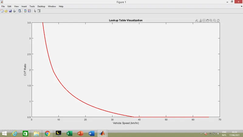
Lookup table:
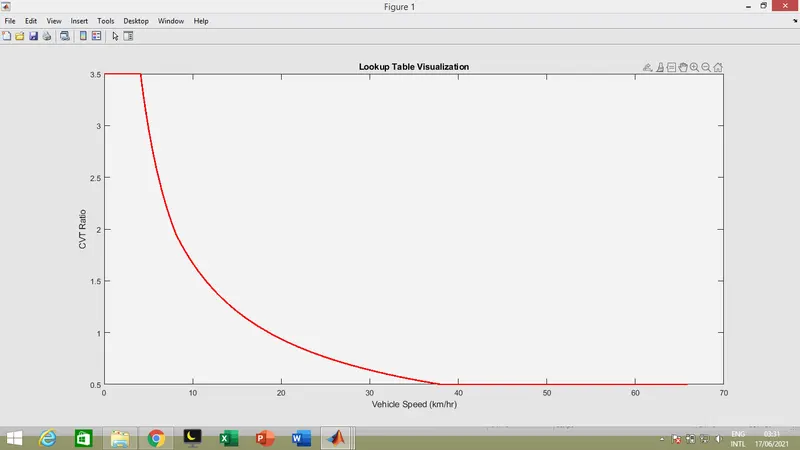
Lookuptable of cvt ratio vs vehicle speed can be visualised from image link generated.
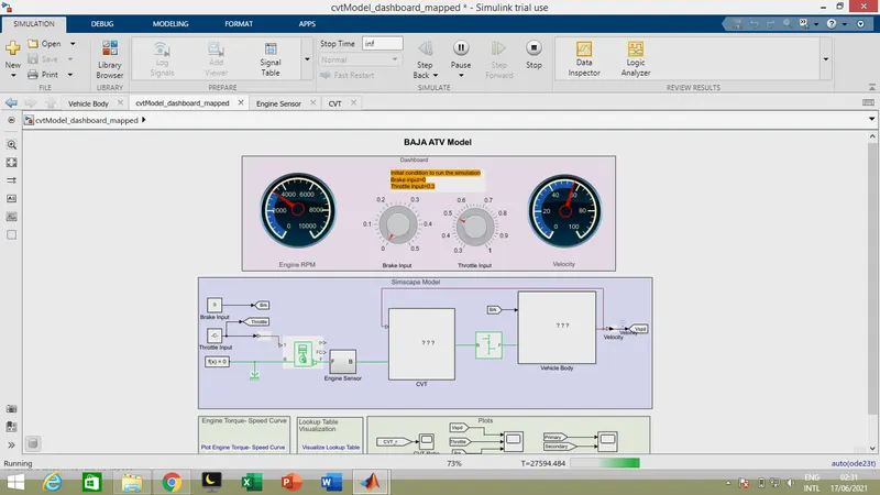
Result:
After running the model we get changes in dashboard with respect to input knob positions.
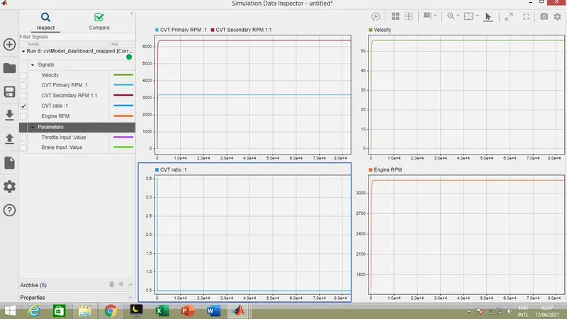
Here shows the result plots of necessary parameters while on running simulation.
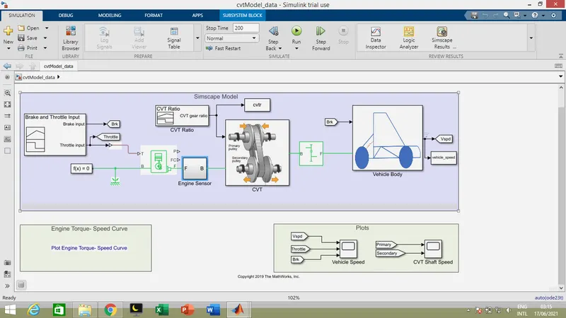
Case 6 :cvtModel_data - This model is used to log the cvt ratio and vehicle speed for the look table visualization.
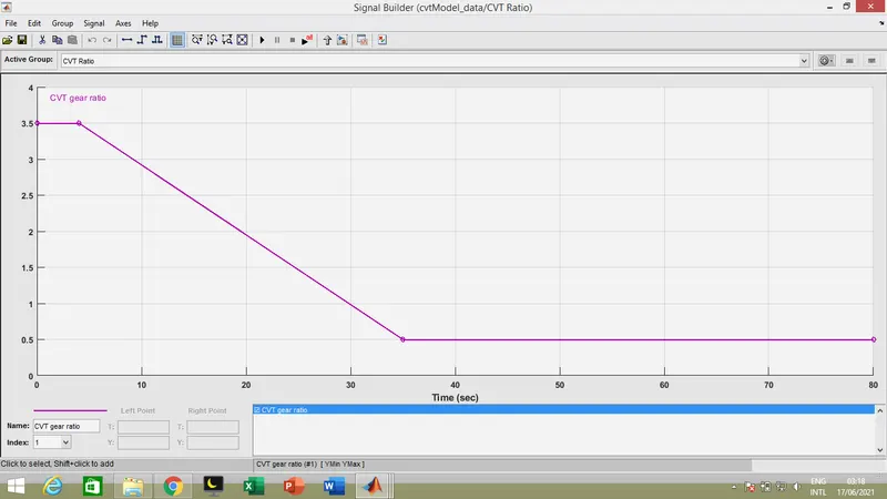
Here in this case the cvt ratio given as signal builder.
Model:
cvt ratio:
Result:
While running the simulation for 200 sec we get the result as shown below,
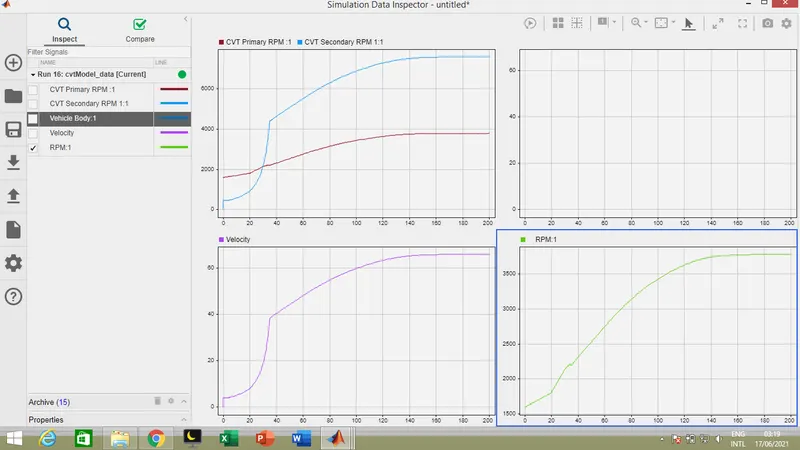
from the results we can compare thr speed of secondary cvt shaft with primary cvt shaft.
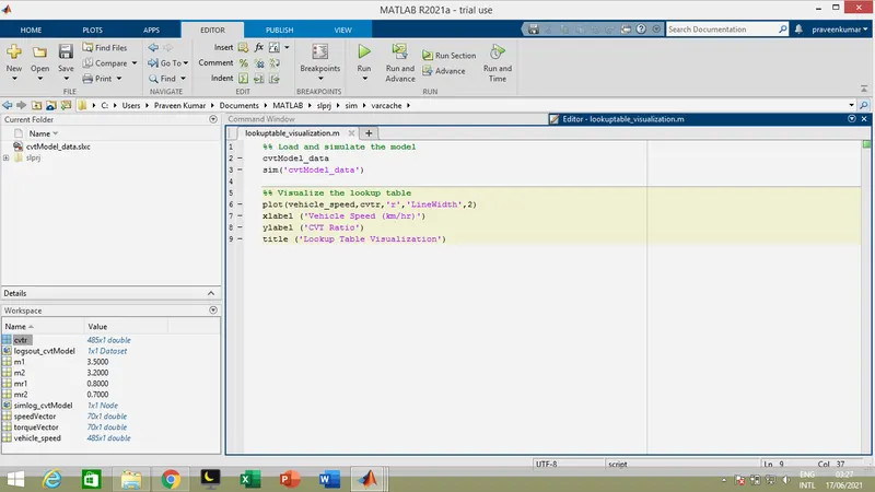
Case 7 : lookuptable_visualization-Script to load and run the model,cvtModel_data.
Here case 6 can be acheived by writing the script for loading cvtModel_data file and run it for the output.
Script:
Result:
The cvtModel_data file gets loaded and run automatically gives is result.
Additionally according to the script lookup table for cvt ratio vs vehicle speed is generated.
Note: Simulation files are attached outside.
Thank you.
Submitted by,
Praveen Kumar L V
Date:16/06/2021