Week - 4(Control logic of washing machine using state flow, Modelling a gear shift using simulink chart)
Week 4 Challenge 7
1)Control logic of washing machine using state flow.
Objective:
To create a logic of wachine machine operations using stateflow chart according to the conditions mentioned.
Conditions:
- If the power supply is available, the system gets activated
- If the Water supply is not available, stop the process & indicate through LED
- Soaking time should be 200s followed by Washing time of 100s.
- Then rinsing happens for next 20s & dryer runs for 50s
After all the processes have completed turn on the finished LED.
Blocks required:
- Constants
- chart
- display(controlling)
- lamp
- scope
Model:
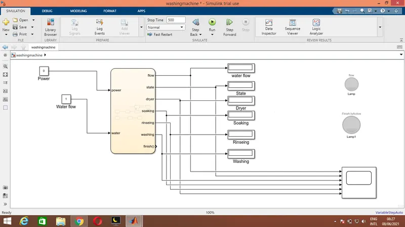
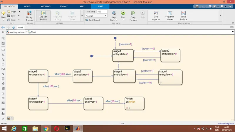
chart:
working :
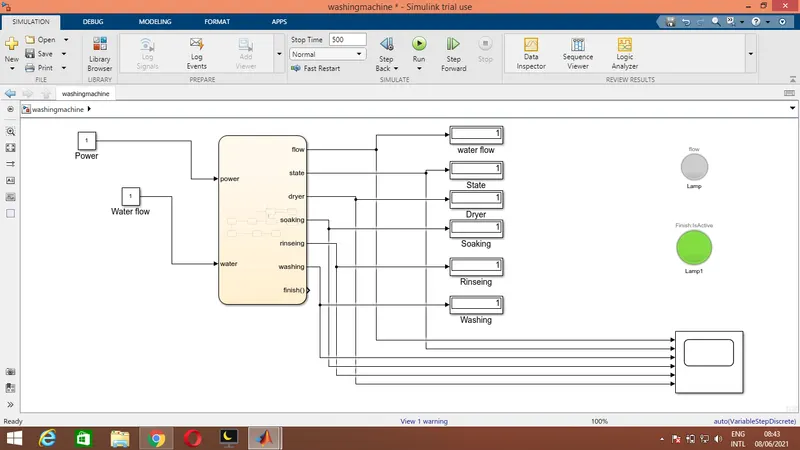
The power input given as 1(on) and water input given as 1(on).
In this condition signal crosses stage1->stage3->stage5->stage6->stage-7->stage8->stage9,then green lamp blows for finishing.
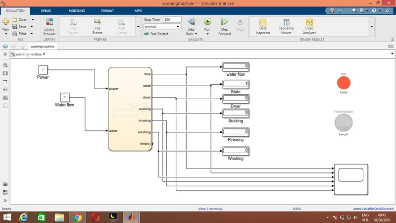
Now power is 1(on) and water is 0(off).
In this condition signal crosses the stage1->stage3->stage4,and stop the further process.Indicating red lamp is blowing.
Here,
stage1=power on stage
stage2 =power off stage
stage3=water on stage
stage4 =water off stage
stage5=soaking stage(for 200 secs)
stage6=washing stage(for 100 secs
stage7=rinseing stage(for 20 secs)
stage8=drying stage(for 50 secs)
stage9=finishing stage.
Result:
Here while,power=1 & water=1
While power=1,water input=0,all process are stopped.
Here showing the result scope while fully finished the process.
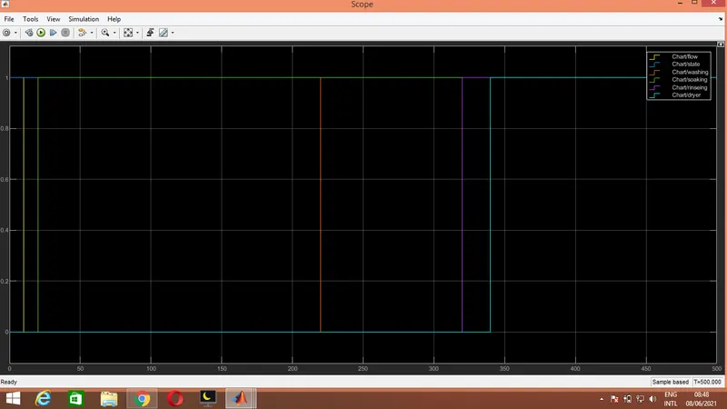
All process are working at their respective time intervals.Hence justified the output.
Note:Model file and output snaps are attached outside.
2)Modelling a gear shift using simulink chart.
Objective:
To construct a gear shifting mechanism model of simulink using chart for its control loops.And justify its output by verifying its gear shift while running simulation.
Given Conditions:
Speed Range(kmph) Gear
0 to 15 1
16 to 25 2
26 to 40 3
41 to 60 4
Above 61 5
Block required:
- constant
- Slider gain
- chart(Forcontrol)
- Display
- Scope
Model:
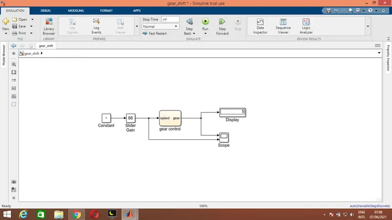
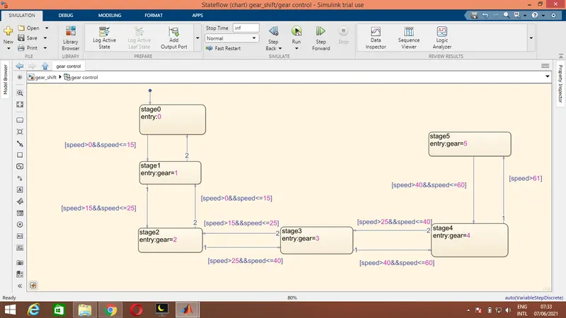
Working principle:
- The variable input is given by slider gain simulink block.
- Then moving into chart section for control logics,speed is declared as variable as input data and gear is declared as output data through chart pane option.
- Here 6 stages are looped namely stage0,stage1,stage2,stage3,stage4,stage5.
- Each transitions from one stage to anotherstage are depends on its input speed value.For every transitions conditions are declared.
- The input speed value enters stage 0 initially,check the condition of stage 1 and stay on until its condition fails.
- Then according to its value satisfies the conditions, the output jumps into that stages.
- The output shows in display varies accordingly to input speed.
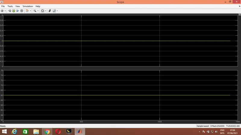
- We can also verify it by scope.
Result:
For example, at speed 66Km/hr the output gear displayed(shifted to) as 5 as per the conditon.Further the real gear shifting video is uploaded in google drive link.
Google drive link: https://drive.google.com/drive/folders/14rznkDBBN1rncHkL3odrYJX2r8nCAg5d?usp=sharing
Thank you.
Sumbitted by:
Praveen Kumar L V
Date:08.06.2021