Week -2(Model for a door bell and observation of plunger motion, Senceing temperature of a heater and On/OFF the fan according to the conditions,
WEEK 2 CHALLENGE 3
1) Model for a door bell and observation of plunger motion.
Objective:
To construct a model for door bell and observe its plunger motion while pressing switch for 2 seconds.
Blocks required:
- Dc voltsge source(Battery) - 24 V
- Switch
- Step input -For switch input.
- Elecrtical referance
- Solenoid With magnetic effects (Subsystem)
- Translational motion sensor
- Mechanical translational referance
- Solver configuration
- PS-Simulink and Simulink-PS converters.
- Display
- Scope (For plunger movement,Input step signal)
Model:
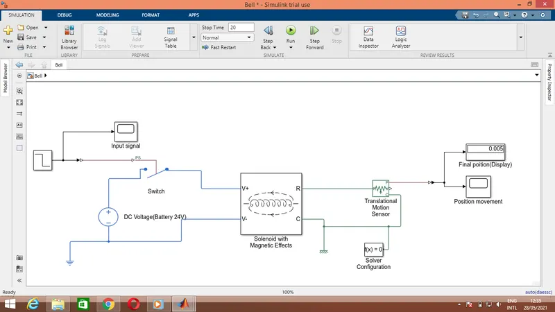
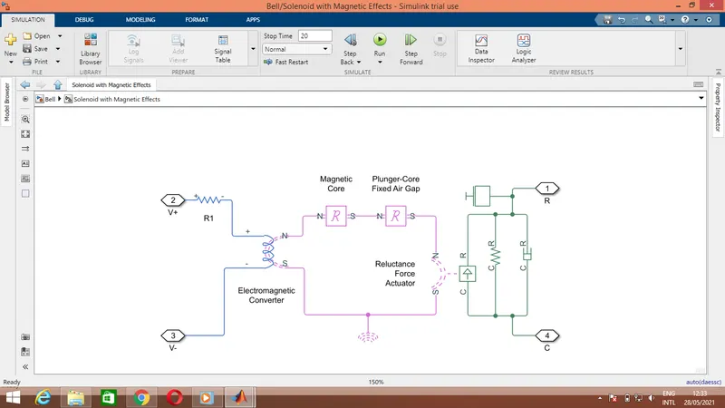
Solenoid subsystem:
Procedure:
- A Dc supply of 24 V given to the Solenoid with magenetic effects system through a swith.Physical signal is given to the switch by a step signal input through simulink to physical converter.
- Time of 2 seconds is given as step input for ON (Switch closed position) and other time as OFF( Switch open position).
- If the step signal greater than threshold value,the switch get closed and vise versa.
- The subsystem of solenoid values are assumed and get configured inside the blocks.
- For example in electromagnetic converter, number of windings have to be mentioned. In Reluctance blocks of magnetic core and plunger core, its length,cross sectional area,relative permiability of materials have to be configured.
- The Plunger circuit is managed by spring damper simscapes connected with magnetic flux attraction by Reluctance force actuator simscape block.
- Finally the movement of the plunger core can be absorbed by Ideal translational motion sensor.The output can be sceen through scope by converting physical output to simulink signals by using the PS-Simulink converter.
Result:
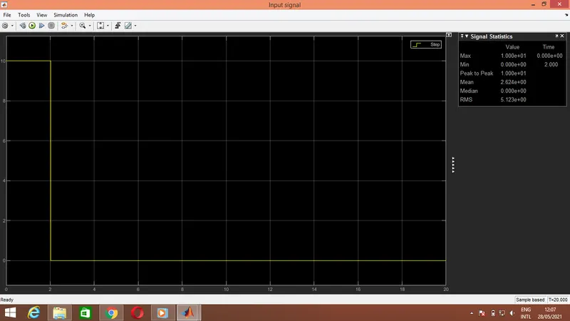
Here shows the step input signal given to the switch.
For (0-2)Seconds the switch get closed as input signal greater than threshold value(10>0.5).
For remaining time switched gets open.
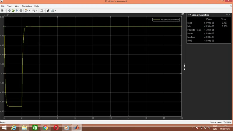
The position of the plunger observed in below snap as output scope.
For (0-2) seconds while the switch in ON condition the position of plunger moved from maximum to minimum position.
Again plunger moved to its orginal maximum position. Here justified from Signal Statistics view.
2)Senceing temperature of a heater and On/OFF the fan according to the conditions.
Objective:
To sence the temperature of a heater and switch ON/OFF the fan according to the given conditions.
Conditions:
Temperature source: 20 °C from 0 to 10 seconds, 27 °C from 10 to 30 seconds, 23 °C from 30 to 50 seconds.
Fan conditions: ON if the temperature above 25 °C, OFF otherwise.
Blocks required:
- Signal builder.
- Fahrenheat to celcious converter.
- Celcious to fahrenheat converter.
- Controlled temperature source.
- Temperature sencor.
- Physical signal switch.
- Dc Voltage source.
- Current sensor.
- PS-Simulink converter.
- Simulink-PS converter.
- Solver Configuration.
- Display,Scope.
Model:
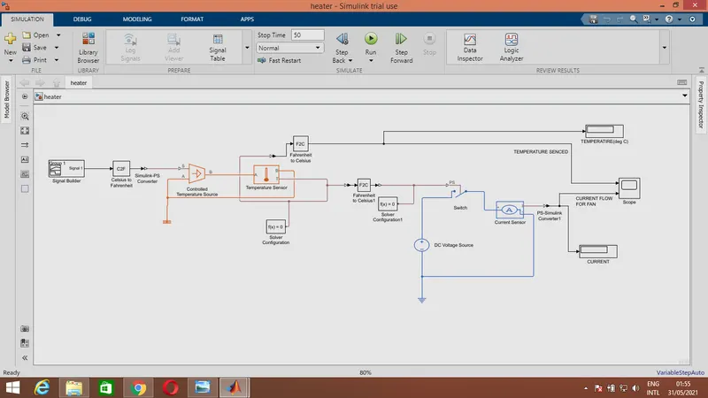
Here attached the snap of model.
Procedure:
- According to the given conditions, inputs with respect to time are generated by using signal builder.Snap get attached outside.
- That signal is converted to fahrenheat by celcious to fahrenheat converter.
- Then this signal is given to controlled temperature source(Heater) and senced using heat sensor(thermistor) ,and converted to celcious by fahrenheat to celcious converter.
- This signal can be viewed in scope(Snap in result).
- This physically senced signal is given to switch which is connected to the fan circuit.
- The threshold is set as 25 degC. Thus according to the continuous input physical signal the switch gets ON and OFF for the circuit of fan.
- The conditions are,(Temperature source: 20 °C from 0 to 10 seconds, 27 °C from 10 to 30 seconds, 23 °C from 30 to 50 seconds.Fan conditions: ON if the temperature above 25 °C, OFF otherwise.)
- The ON and OFF of the switch can be senced from using a current sensor in the circuit.
- 0 Amps for OFF condition.(With respect to switch open conductance).
- 10 Amps for ON conditon.(With respect to switch closing resistance).
Result:
1st graph:Temperature senced by temperature sensor.(Thermistor)
For (0-10) seconds the output temperature is 20 degC.
For (10-30) seconds the output temperature is 27 degC.
For (30-50) seconds the output temperature is 23 degC.
2nd graph: Current senced in fan circuit.
For (0-10) seconds the current in fan circuit is almost 0Amps at 20 degC,which shows the fan is in OFF condition.
For (10-30) seconds the current in fan circuit is 10Amps at 27 degC, which shows the fan gets ON.
For (30-50) seconds the current in fan circuit is almost 0Amps at 23 degC,which shows the fan again moves to OFF condition.
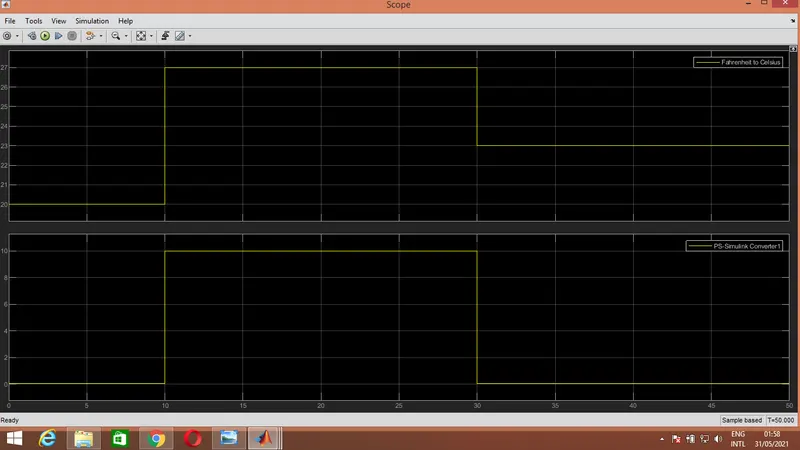
Hence the output get justified as fan gets ON for above 25 degC.
Thank you
Submitted by: L V Praveen Kumar
Date: 31.05.2021