Week 8 Challenge
Week 8 Challenge
Ultracapacitor
Aim:
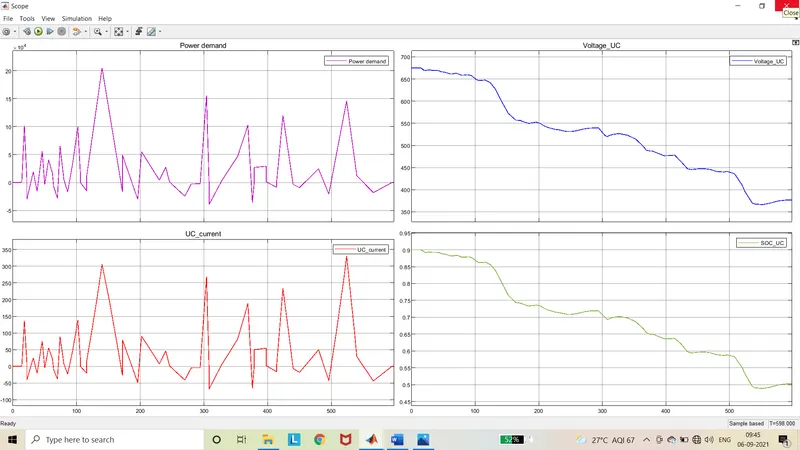
To model the energy storage device as ultracapacitor and analyze its operating characteristics according to the power demand by running the model for 598 seconds.
Ultracapacitor:
An ultracapacitor (SC), also called as supercapacitor, is a high-capacity capacitor with a capacitance value much higher than other capacitors, but with lower voltage limits, that bridges the gap between electrolytic capacitors and rechargeable batteries. It typically stores 10 to 100 times more energy per unit volume or mass than electrolytic capacitors, can accept and deliver charge much faster than batteries, and tolerates many more charge and discharge cycles than rechargeable batteries.
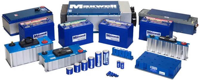
Ultracapacitors complement a primary energy source which cannot repeatedly provide quick bursts of power, such as an internal combustion engine, fuel cell or battery. The future horizon looks brilliant for ultracapacitors, which already rank as a powerful alternative energy resource. Its unique performance characteristics make them ideal for capturing and storing braking energy generated in trains, trams, trucks and automobiles – and then releasing it on demand.
Supercapacitors are used in applications requiring many rapid charge/discharge cycles, rather than long-term compact energy storage in automobiles, buses, trains, cranes and elevators, where they are used for regenerative braking, short-term energy storage, or burst-mode power delivery.
Advantages:
- Environmentally safe
- No toxic chemicals
- Virtually maintenance free
- Long life
- Operating temperature range -40°C to +65°C
- Higher energy vs. electrolytic capacitors
- Higher power vs. batteries
- Resists shock and vibration
Software used:
- MATLAB / Simulink
Blocks used:
- Constant
- Signal builder
- Integrator
- Product
- Divide
- Add
- Square
- Sqrt
- In
- Out
- Scope
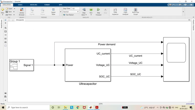
Model:
Procedure:
- Signal builder block is used as a power demand source.
- In the Ultracapacitor subsystem, current and voltage calculation subsystem and SOC calculation subsystem is
- In the charge and voltage calculation subsystem, the current, voltage, open circuit voltage and charge calculation subsystem is formed.
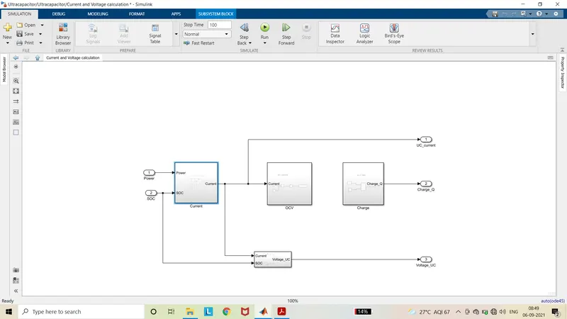
- The input to the current subsystem is Power demand from the signal builder and feedback from the SOC.
- The current calculation is done by using the formula,
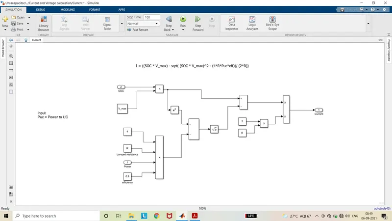
`I = ((SOC*V_max-sqrt((SOC*V_max)^2-(4*R*P_uc*eff)))/(2*R))`
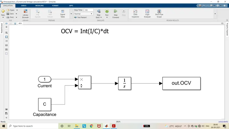
- The input to OCV subsystem is current. The Open circuit voltage is calculated by using formula,
`OCV = int(I/C)dt`
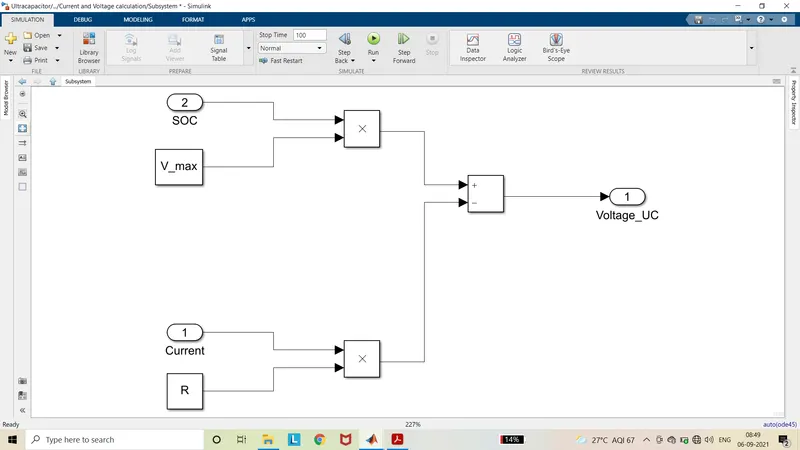
- The input to voltage subsystem is current and SOC. Voltage is calculated by using formula,
`V = (SOC*V_max)-(I*R)`
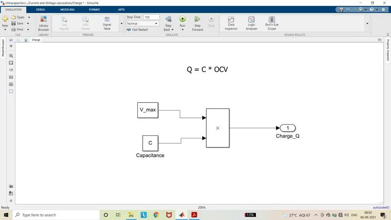
- The charge can be calculated by using formula,
`Q = C*V_max`
- The input to the SOC calculation subsystem is current and charge. The SOC is calculated bu using formula,
`SOC = int((I*eff)/Q)dt`
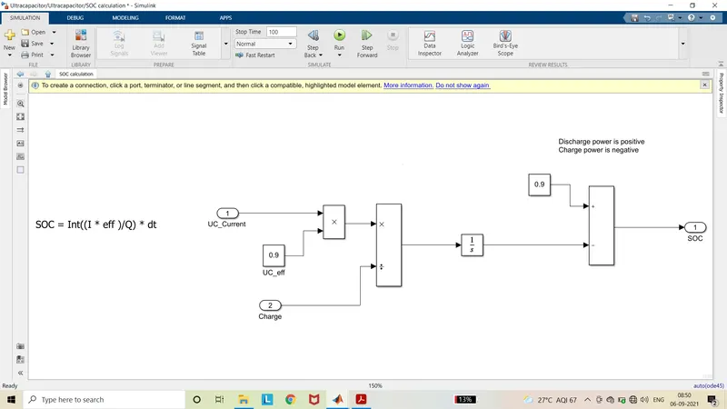
- Then the calculated SOC is subtracted from the Initial SOC to get the instantaneous SOC.
- The current, voltage and SOC are connected to scope to visualize the result.
Parameters:
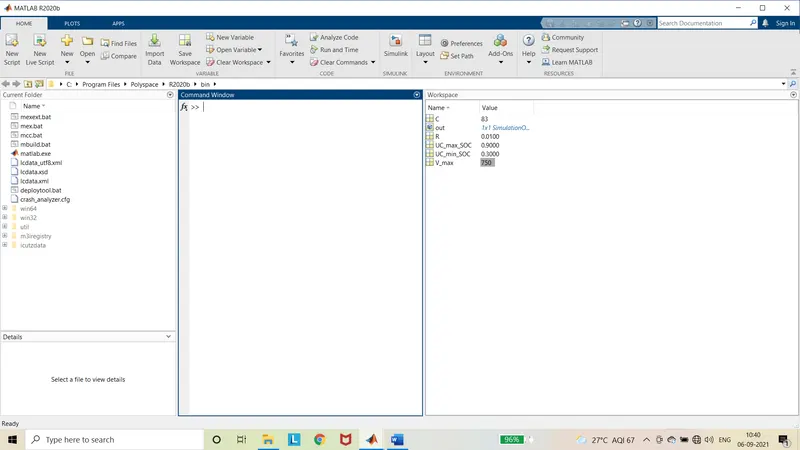
The parameters are loaded in the MATLAB. The parameters are obtained from the datasheet.
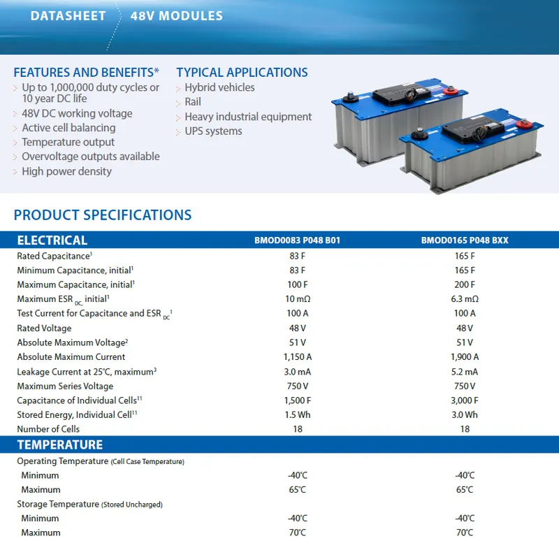
- For the reference, BMOD0083 P048 B01 is taken.
Output:
Scope:
Summary:
From the above plots it is observed that, when there is a sudden peak load power demand of above 200kW is required. It can be met by the met by ultracapacitor without any tension. It can also be charged quickly to particular value with less amount of power of less than 50kW. It can also be able to meet sudden peak three to four times the normal. For example, if the electric vehicle’s normal load is less than 100kW and only the peak loads is about 600kW. Then only by going with battery to meet this demand. The battery pack has to designed for 600kW. Then cost of the vehicle is rapidly increases. Because, only for the short period of time only peak load occurs. For that short duration of time, it is unnecessary to increase the battery pack which increases cost and weight of vehicle. Let us consider by going on designing only with fuel cell. The fuel cell has the operating range in the polarization cure. If the fuel cell vehicle is operated above or below that operating then the efficiency of the vehicle is very poor. In order to overcome these shortcomings, the ultracapacitor is used. It can be able to deliver the sudden peak load which can be three to four times the normal load. So the 100kW load can be met by battery and 600W or more peak load can be met by ultracapacitor. This can be shown in below plot.
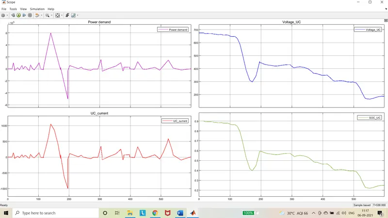
The sudden load of 600kW can be delivered by ultracapacitor and regenerative load of 500kW can also be used for charging.