Week -2
1. Simulink model of Doorbell using solenoid block
Objective:
To simulate a model for bell and to observe the position of the plunger.
Blocks Used:
- Battery
- Solenoid
- Switch
- Step
- Electrical reference
- Simulink-PS converter
- PS-Simulink converter
- Ideal Translational Motion sensor
- Mechanical Translational Reference
- Solver Configuration
- Scope
Model:
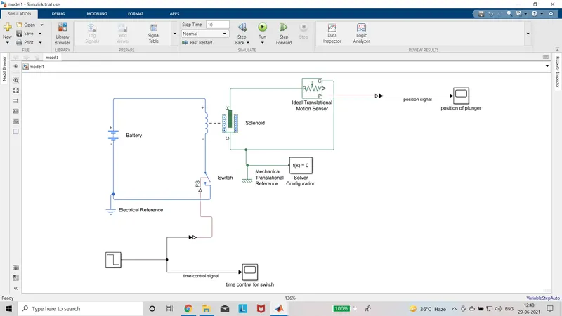
Description:
- Add the blocks required for the model.
- Make connection accordingly.
- Configure the parameter values to the blocks.
- The value of the battery is set equal to the rated voltage of the solenoid. i.e)50V
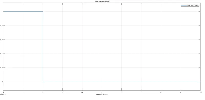
- The external time control for the switch is made by connecting the step input with the on time for 2 seconds.
- The position of plunger is observed by connecting Ideal Translational Motion sensor and scope.
Result:
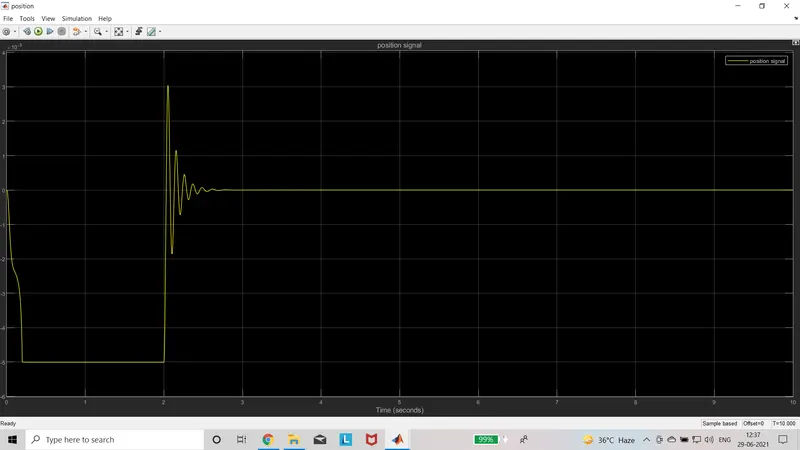
When the switch is closed, the coil wounded on the core is excited by battery and produces the magnetic attraction force. The plunger arrangement consists soft iron core, spring and damper. The soft iron core of the plunger is attracted to the magnetic core during the on time. After the position of plunger is damped by using damper.
Output:
Time control for Switch
Position of Plunger
2.Simulink model for Temperature controlled fan using thermistor
Objective:
To simulate the model to control the On and Off state of fan using thermistor.
Blocks Used:
- Signal builder
- Controlled temperature source
- Thermistor
- Battery
- Resistor
- Voltage sensor
- PS-Simulink converter
- Simulink-PS converter
- Switch
- Constant
- Controlled dc voltage source
- Dc motor
- Ideal Rotational motion sensor
- Mechanical Rotational reference
- Electrical reference
- Thermal reference
- Scope
- Display
Model:

Description:
- Add the blocks required to the model.
- Make connections as required for the model.
- Configure the parameters for the blocks.
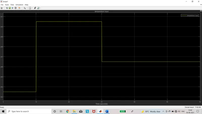
- The Signal builder block is configured by giving the Temperature input. i.e) 293.5K for 0 to 10 sec, 300.5K for 10 to 30 sec and 296.5K for after 30 sec.
- This input signal is given to the Controlled temperature source.
- One input of the thermistor is connected to Controlled Temperature Source and other is connected to the Battery.
- Thermistor Is used to sense the accurate change in temperature for certain limits.
- When the temperature changes the resistance value of thermistor also changes depending upon the temperature coefficient.
- Here Negative temperature coefficient is used, so when the temperature increases the value of resistance decreases.
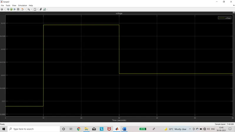
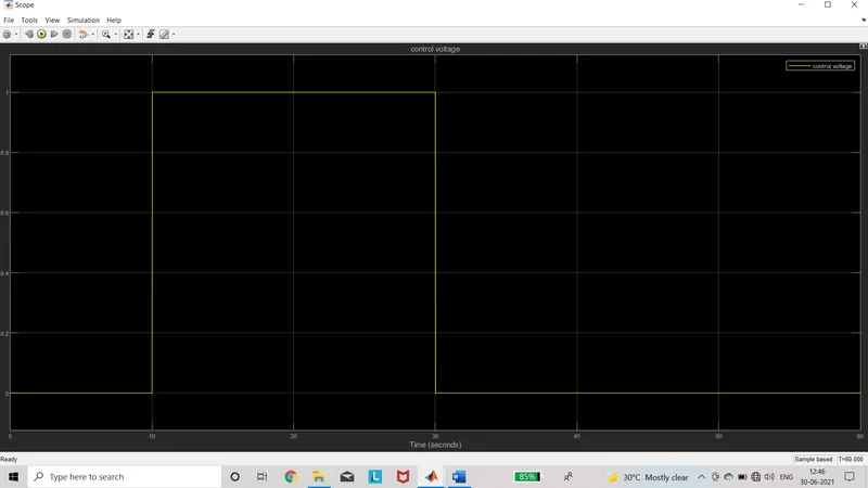
- Voltage divider (Resistor) is connected to thermistor and voltage across the resistor is sensed by voltage sensor. This sensed value is given as control voltage to switch.
- The output of the switch is the control input for Controlled dc voltage for Fan (dc motor).
- The State of fan is observed by using Ideal Rotational motion sensor and Scope.
Result:
During 0 to 10 seconds the temperature is 23 degree Celsius, the fan is Off.
During 10 to 30 seconds the temperature is 27 degree Celsius, the fan is On.
After 30 seconds the temperature is 25 degree Celsius, the fan is Off.
Temperature Input Scope:
Voltage Output Scope:
Control Value for Controlled Dc Voltage:
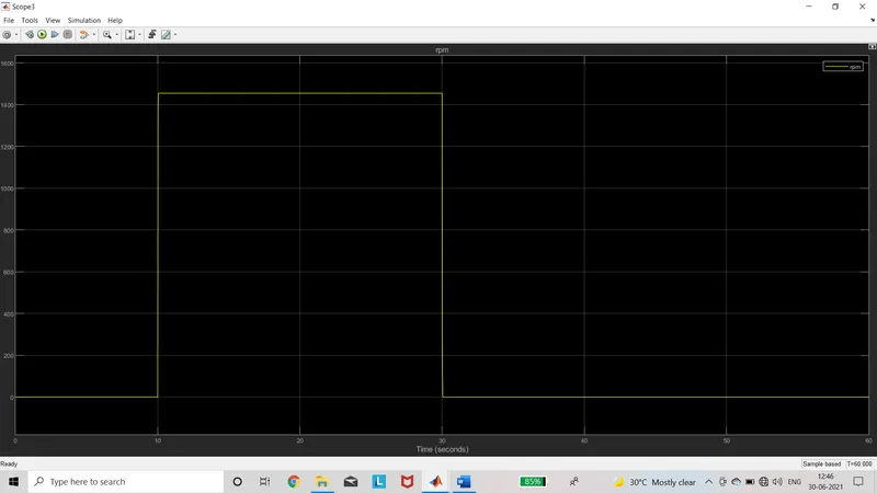
Speed of Fan: