Week - 4
1.Control logic for Washing machine using Stateflow:
Objective:
To implement the control logic for a washing machine using stateflow by the given sequence.
Blocks used:
- Constant
- Chart
- Lamp
- Scope
Model:
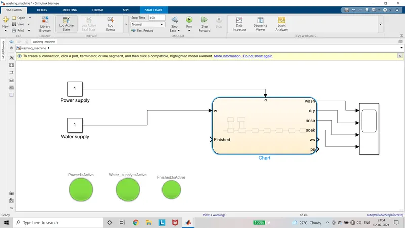
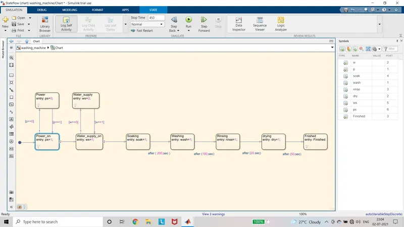
Description:
- Add the blocks Required to the model.
- Connections are made as per the model.
- Configure the parameter values to the blocks.
- In Chart block, the states are added for power supply, water supply, soaking, washing, rinsing, drying and finish.
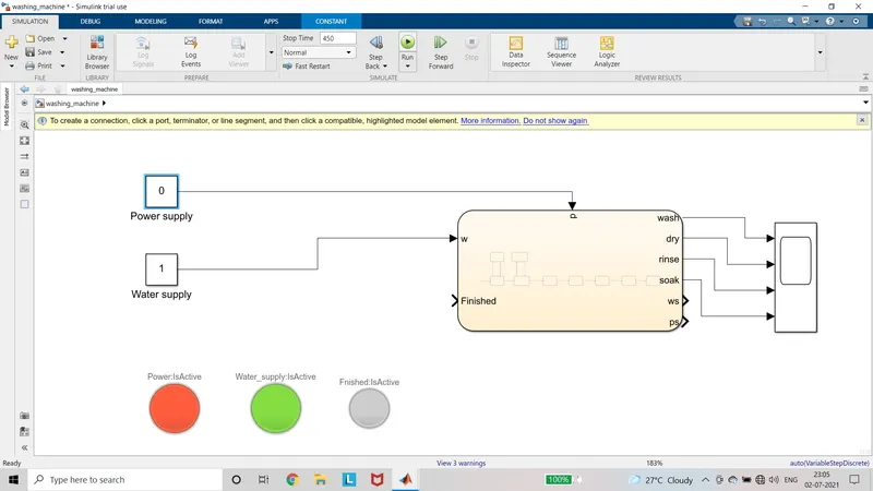
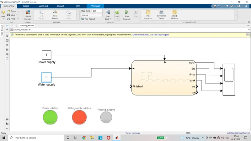
- The power supply is checked by using the condition and it is connected to lamp. If the power supply is 1 the lamp will glow in green else power supply is 0 the lamp will glow red.
- The water supply is checked by using the condition and it is connected to lamp. If the water supply is 1 the lamp will glow in green else water supply is 0 the lamp will glow red.
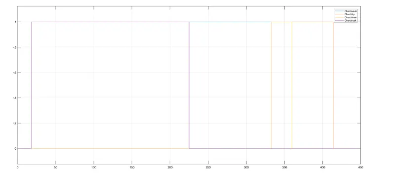
- The entry value of Soaking state is given as 1 and exit value is given as 0. And after (200, sec) condition is used to activate soaking for 200 seconds.
- The entry value of Washing state is given as 1 and exit value is given as 0. The washing is state is active for 100 seconds by using condition after (100, sec).
- The entry value of Rinsing state is given as 1 and exit value is given as 0. The rinsing is state is active for 20 seconds by using condition after (20, sec).
- The entry value of Drying state is given as 1 and exit value is given as 0. The washing is state is active for 50 seconds by using condition after (50, sec).
- Then Finished state is active and it is connected to the lamp.
Result:
- If the power supply is given as 0, the power lamp glows red and if the water supply is 1 then the water supply lamp glows as green or else it glows red. And the logic does not execute.
- If the power supply is given as 1, the power lamp glows green and water condition is checked. If the water supply is 1 it glows green and if 0 the lamp glows red. And the logic does not execute.
- If both power supply and water supply is 1, then all the states execute and Finished lamp is glow as green.
Output:
2.Simulink Chart for Gear Shift logic:
Objective:
To create a Simulink chart for gear shift logic according the Speed given while running.
Blocks used:
- Constant
- Slider gain
- Chart
- Display
- Scope
Model:
Description:
- Add the blocks Required to the model.
- Connections are made as per the model.
- Configure the parameter values to the blocks.
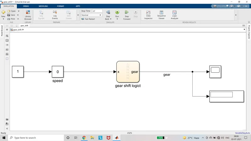
- The input speed is given to the x port of the chart.
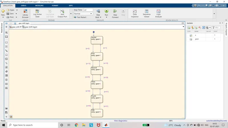
- Initial State is given as neutral if the speed is 0.
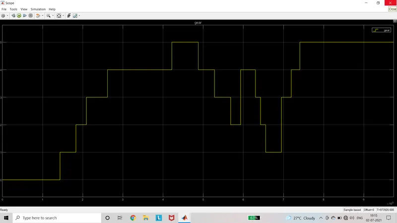
- If the speed is in the range 1 to 15, the state first is active and gear is 1.
- If the speed is in the range 16 to 25, the state second is active and gear is 2.
- If the speed is in the range 26 to 40, the state third is active and gear is 3.
- If the speed is in the range 41 to 60, the state fourth is active and gear is 4.
- If the speed is above 60, the state fifth is active and gear is 5.
- The gear state is displayed in the display.
Result:
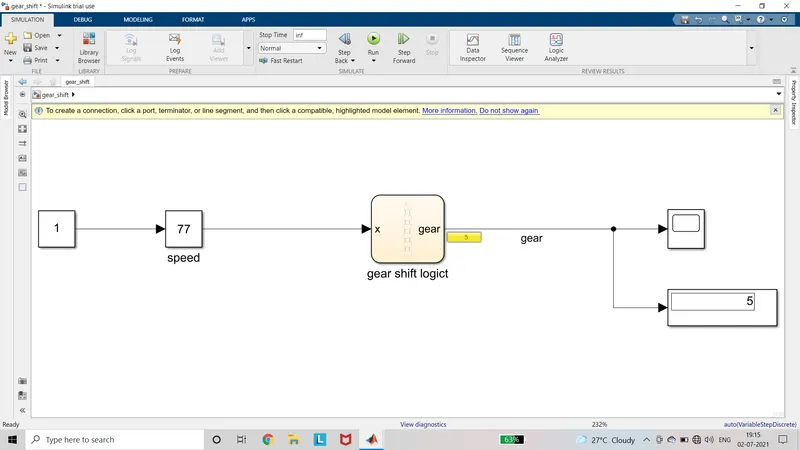
The run time is set to infinity and run the model. While running the speed is varied by using the slider gain and the gear position is displayed in the display. The position of gear in each speed is obtained in the scope.
Output:
Drive link:
https://drive.google.com/drive/folders/1kC9cvpXu3jAcX9R028xKt9bX1xVdcsKt?usp=sharing