Project
Aim:
To study about the BAJA All Terrain Vehicle(ATV) model using Continuous Variable Transmission(CVT) by implementing various parameters.
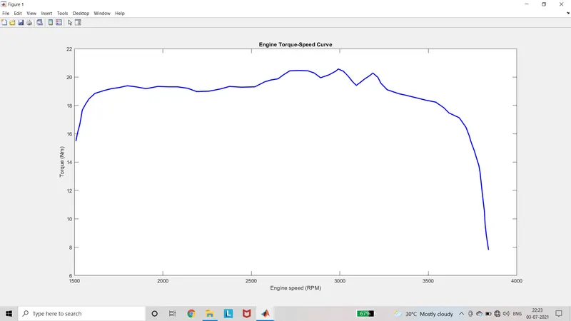
To observe the velocity of vehicle, rpm of engine, Speed-Torque Characteristics, CVT ratio, Brake, Throttle, speed at primary and secondary pulley of CVT.
To observe the performance of vehicle in various situations such as Hill climbing, tire thrust and wind velocity.
To study about various model configurations of CVT ratio by using signal builder and Lookup table.
Blocks used:
Signal builder
Generic Engine
Engine Sensor
Mechanical rotational motion sensor
Mechanical rotational reference
Mechanical translational motion sensor
Mechanical translational reference
PS terminator
PS-Simulink Converter
Simulink-PS Converter
Variable ratio gear
Simple Gear
Goto
From
Port
Scope
Vehicle body
Tire(magic formula)
Gain
Double shoe Brake
Inertia
Lookup table
PS lookup table
Dashboard
Circular gauge
Knob
Description for Working:
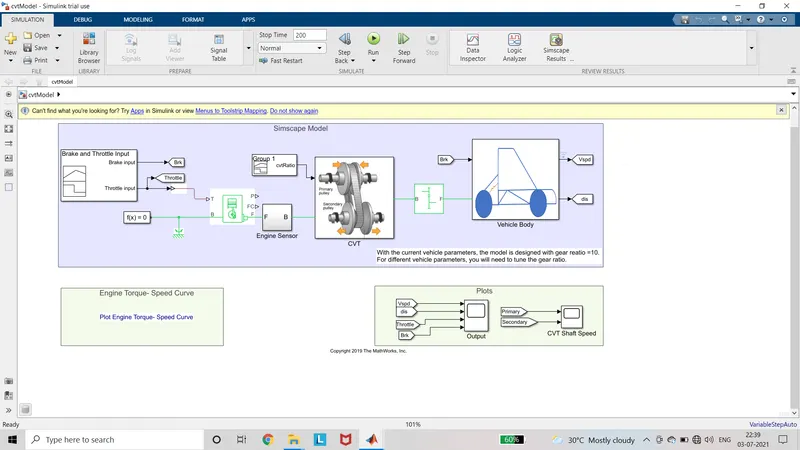
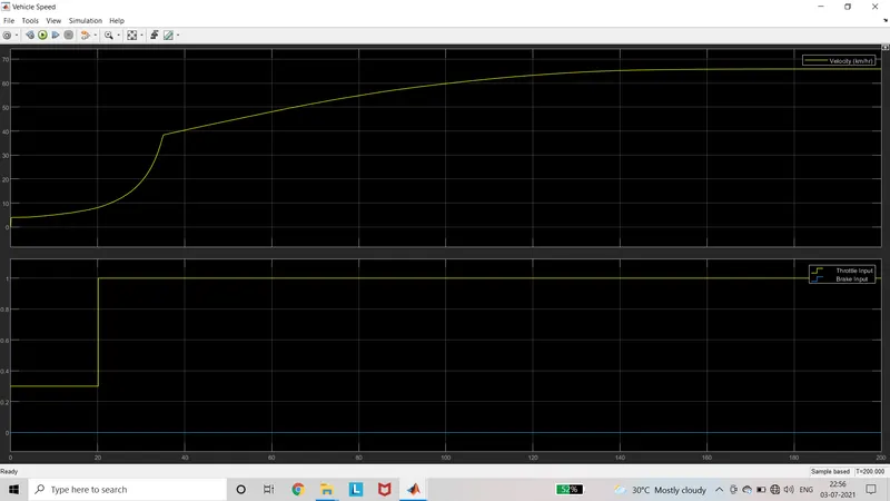
Initially the input for brake and throttle is given by signal builder.
The throttle value is given between 0 to 1. If the value is more than 1 the simulation gives error.
This value is given to throttle input of the generic engine. The case of engine is connected to the mechanical rotational reference and solver configuration.
The follower output is given to the engine sensor. The engine sensor output is crankshaft speed.
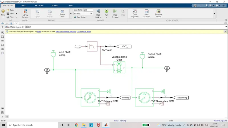
This Crankshaft speed is given to the input of the variable ratio gear(CVT) of the Subsystem CVT.
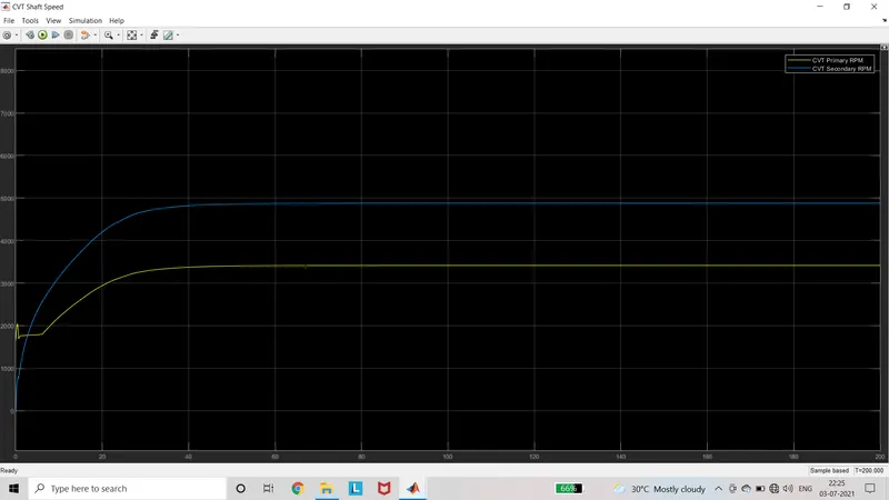
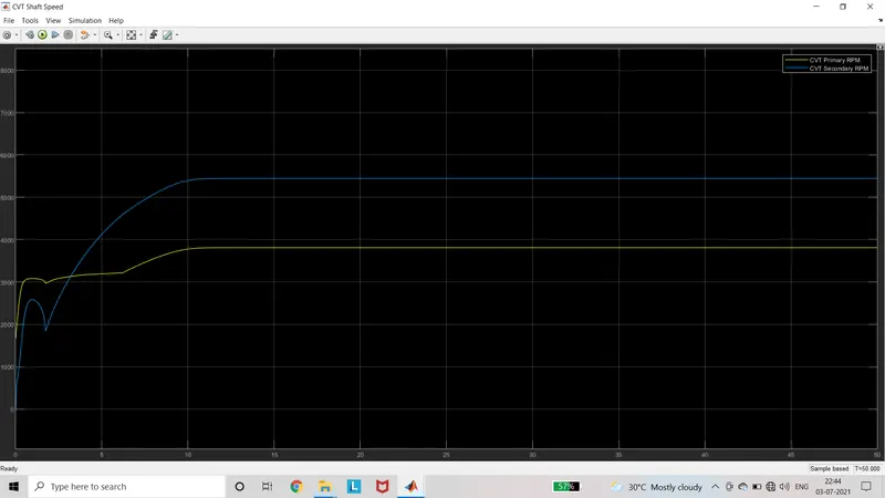
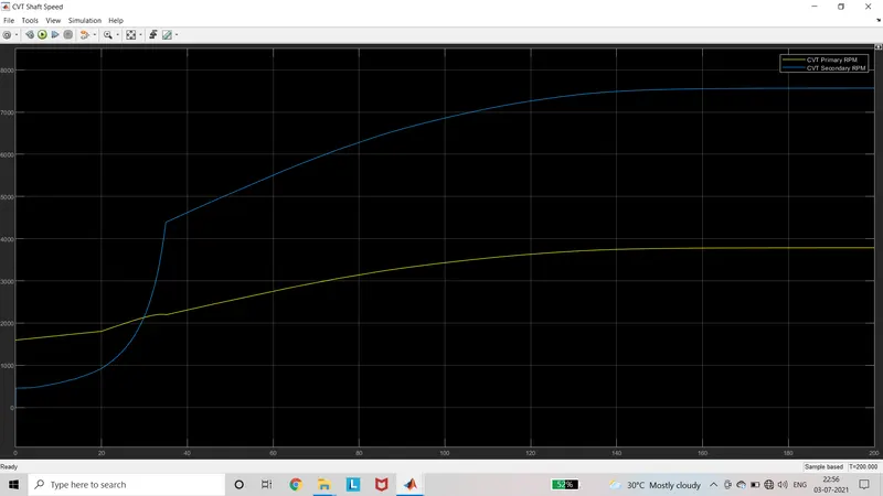
The rotational motion sensor is connected to the both sides of variable ratio gear to measure the primary and secondary pulley rpm.
The signal builder is used for CVT ratio for the variable ratio gear.
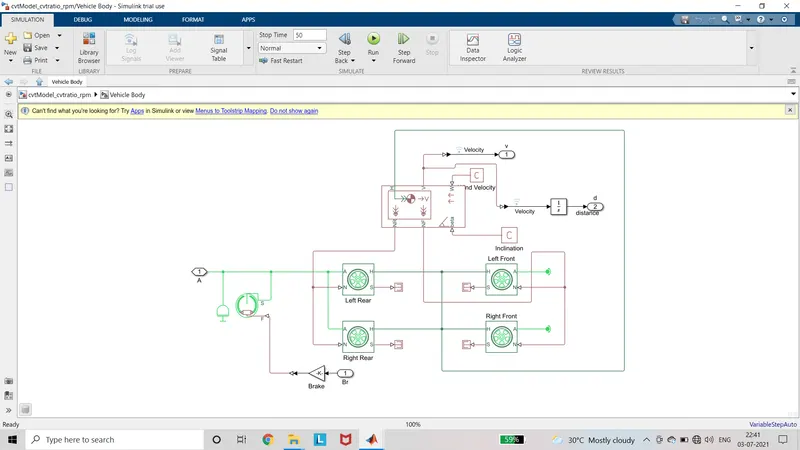
The output signal from the CVT subsystem is given to the rotational conservative part of the wheels of vehicle body subsystem.
The brake signal through gain is given to the actuator present Double cylindrical brake which in active is used to reduce the speed and is connected to the signal from the secondary pulley of CVT to wheel.
The port S of the wheel is the Slip value of tire is connected to PS terminator.
The port H of the wheel is connected to the H port of the vehicle body which gives the value of thrust experienced in the tire.
The port N of the wheel is rear wheel is connected to NR port of vehicle body. The port N of the front wheel is connected to the NF of the vehicle body. The NF and NR signal that gives the force to the wheel, if the force on the wheel is downwards then vehicle moves forwards or if the force is upwards then vehicle moves backwards.
The input of beta in vehicle body is Inclination which is given from PS constant block. It is used for hill climbing.
The input of w in vehicle body is wind velocity which is given from the PS constant block.
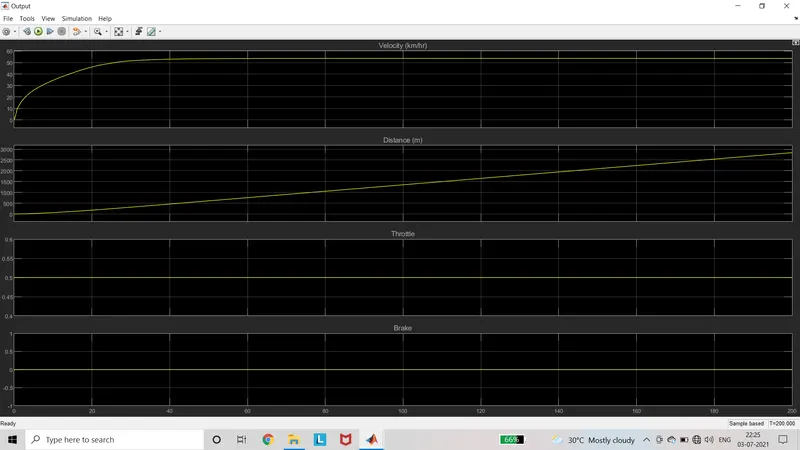
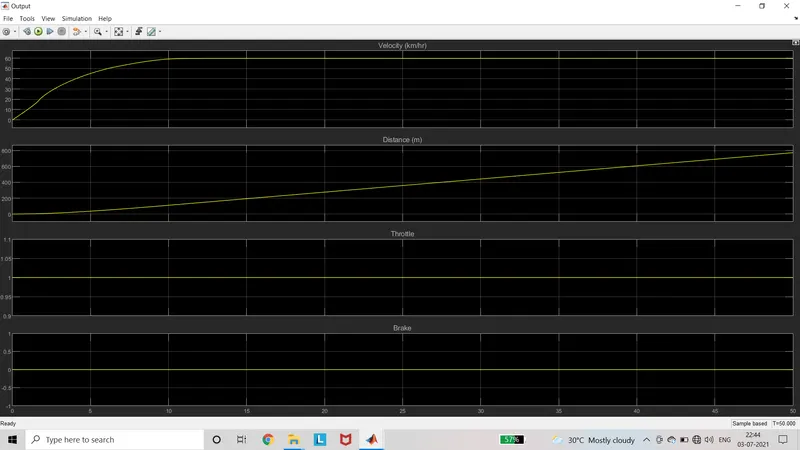
The output of the vehicle body is the velocity which is given to scope.
The velocity signal is given to integrator, its output gives the displacement.
Summary of various cases:
Case1: cvtModel
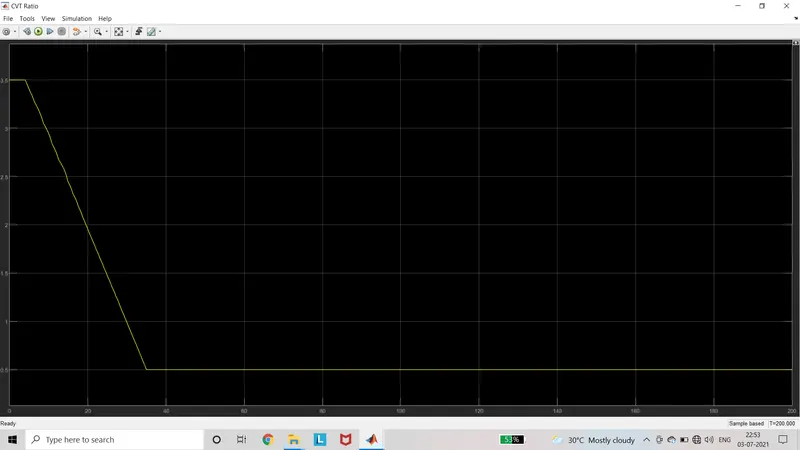
In this case, the cvt ratio value is given by the signal builder. According to cvt ratio the speed from the secondary pulley varies. As the cvt ratio decreases the value of speed increases. The speed of engine and the primary pulley is always same.
Case2: cvtModel_dashboard
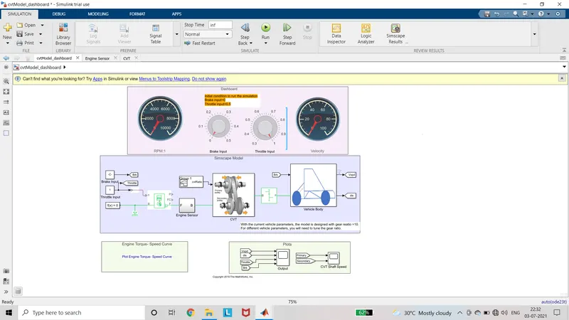
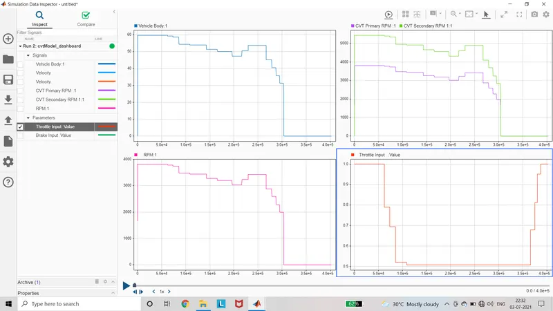
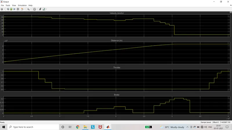
This case is same as the before with the addition of dashboard. The dashboard has the speedometer, rpm and knob for throttle and brake. The throttle and brake can be varied while running the model.
Case3: cvtModel_cvtratio_rpm
In this case the cvtratio is given by the 1D lookup table. Other than that all are same as case1. The datas are fed to lookup table by Lt_cvtratio_rpm.mat file.
Case4: cvtModel_mapped
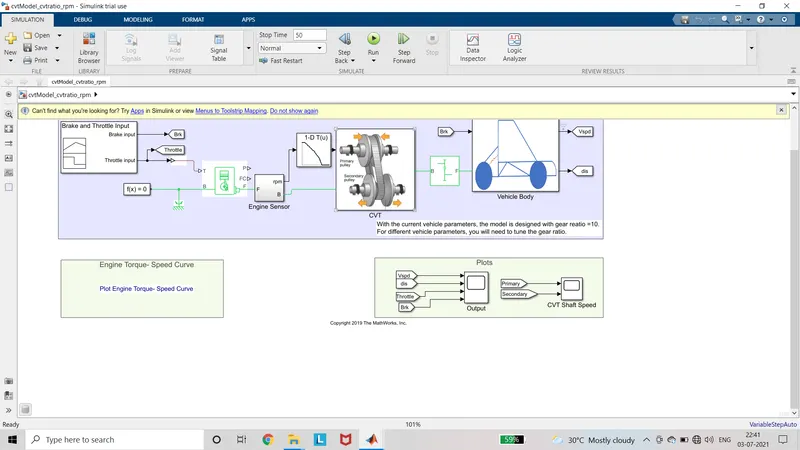
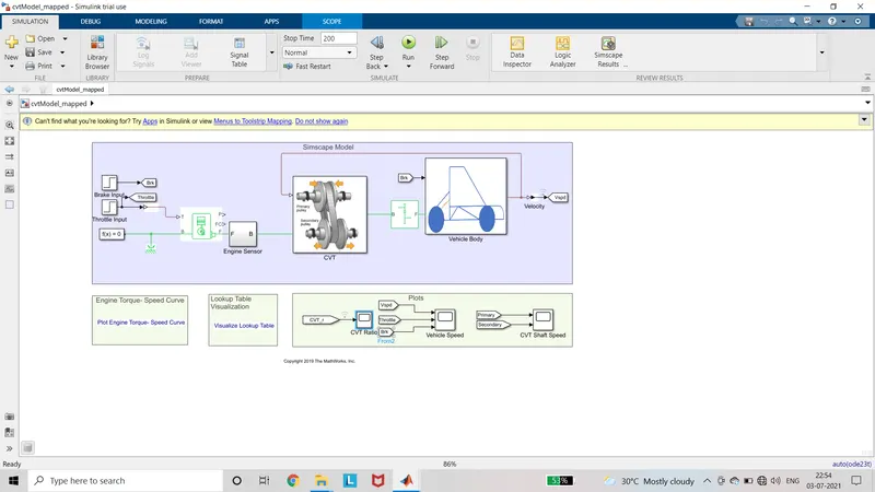
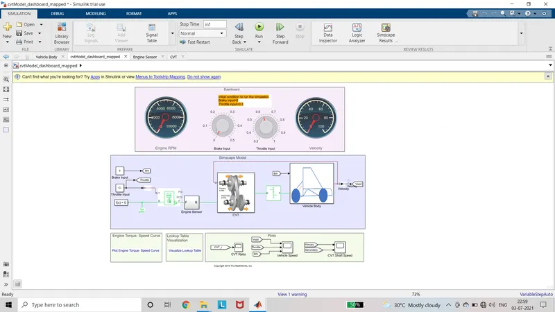
In this case the cvt ratio is fed by the PS lookup table. The input to the lookup table is feedback velocity of the vehicle. The cvt ratio is computed by velocity/3.6 .
Case5: cvtModel_dashboard_mapped
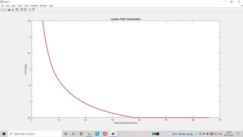
This case is same as case4 except dashboard. The functions of this same is as before. When we want to vary the input while running, the stop time is set as infinity. The rpm, speed, throttle and brake values are obtained in the dashboard itself. The lookup table can be visualized by Lookup table visualization block.
Case6: cvtModel_data
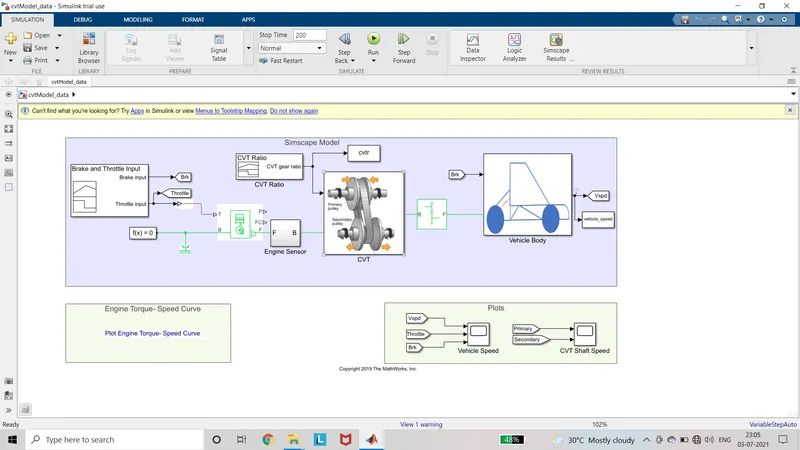
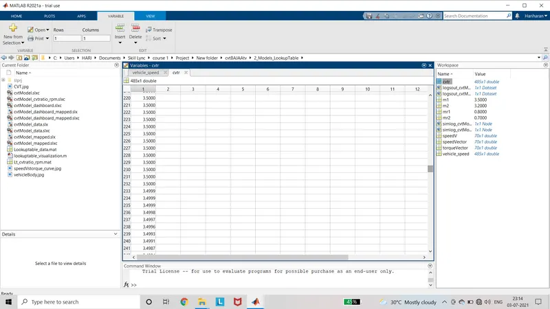
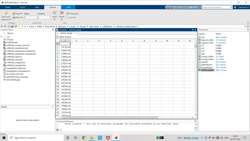
In this case, the cvt ratio values are given by the signal builder and the values are stored in the workspaceas cvtr.The values of vehicle speed is stored in the workspace as vehicle_speed. These stored values can be viewed in the workspace. The values are visualized by scope for secondary and primary shaft speed, velocity and rpm.
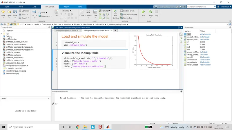
Lookup table visualization
When the lookuptable_visualization.m file is opened it opens as a matlab code. When the code is run, the cvtModel_data model is opened. It shows the plot of vehicle speed vs cvtratio in x axis and y axis respectively.
Drive Link:
https://drive.google.com/drive/folders/1kC9cvpXu3jAcX9R028xKt9bX1xVdcsKt?usp=sharing
Result:
As observed from the all cases, the speed is inversely proportional to the cvt ratio. When the cvt ratio decreases with respect to time the speed increases. While increasing the brake value the speed reduces accordingly. The performance of various models are observed and explained.