Week 8 Challenge
1. Calculate dead load in design report based on IS code and apply dead load on the model
- Finishes of 50mm
- Slab thickness as per the design
- Brick wall load
- Roofing load
AIM : To calculate dead load in design report based on IS code and apply dead load on the model
TOOLS REQUIRE : Manage properties, slabs, properties window, load, load cases, dead load, arae load, full UDL, line load, Validation
PROCEDURE :
- Firstly open previous project file
- Now select load option from tool bar and then select load cases then a pop up window appears
- Now select area load and give its value as 1.2 KN/m2 and select all the slabs
- Now then select full UDL and apply dead load accordingly to all the beams
- Now select line load and apply wall load accordingly in all floors
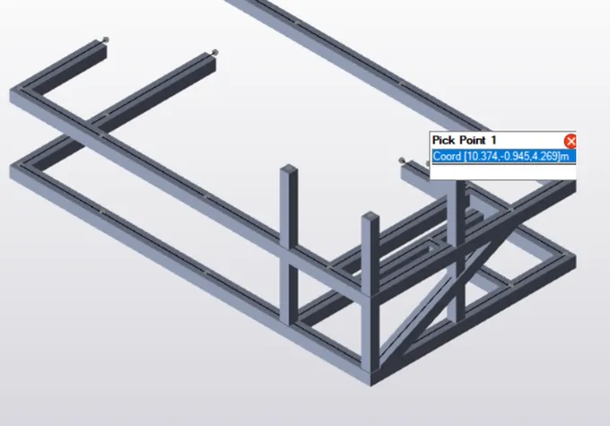
- Now design staircase with accurate measurments
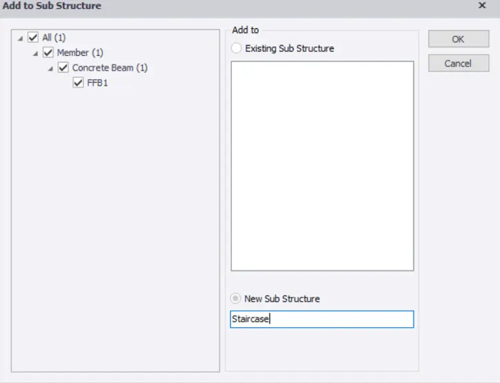
- Now to create stairs we should select all the components and make them all under a substructure and name it as staircase
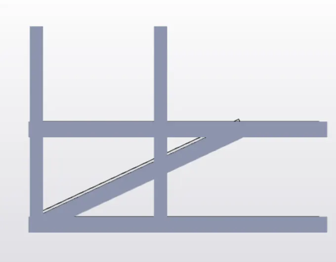
- Then add slope to the staircase using sloped plane option
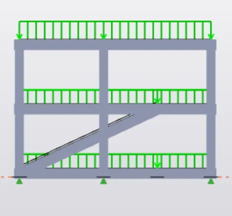
- Now apply area load to the staircase
- Now validate the model and check for any errors
CALCULATIONS :
DEAD LOAD :
Slab load = Model slab in software
Finishes loading (50THK) = 0.05m x 24 KN/m3 = 1.2 KN/m2
Brick wall with cement plaster thickness = 150mm
Unit weight = 20 KN/m3
Floor height (GF to FF) = 5.2 m
Brick wall loading = 15.6 KN/m
Floor height (FF to Roof) = 6.8 m
Brick wall loading = 20.4 KN/m
Roof loading = 1.5 KN/m2
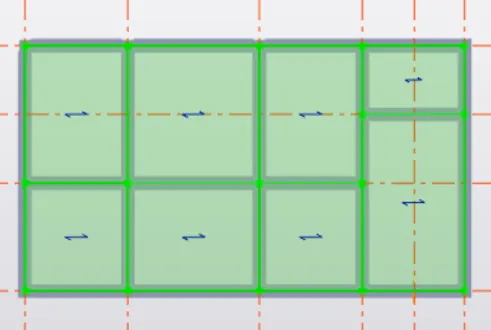
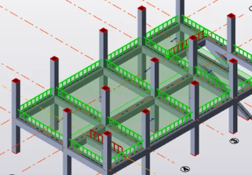
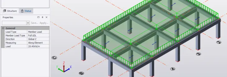
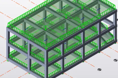
RESULT : Therefore dead load is calculated and applied successfully on the model using above procedure
2. Calculate live load in design report based on IS code and apply dead load on the model
AIM : To calculate live load in design report based on IS code and apply dead load on the model
TOOLS REQUIRE : File, Open, Save as, Load combinations, Load cases, IS code, Validate, Scene content, Area load, Property browser, Project work space
PROCEDURE :
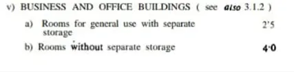
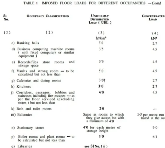
- CALCULATION OF LIVE LOAD IN DESIGN REPORT BASED ON IS CODE
IS 875(PART 2)
Apply Live Load on the Model :
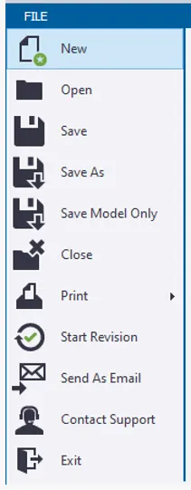
- Open previous project file by selecting open tool from file menu
- Now select load cases option from load tool bar and then select add new load and select it as imposed load
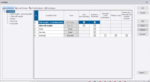
- Now select live load option from pop up window
- Now select area load option and define loads as per IS code book and give values accordingly
- Now select load value to be applied is 4.5 kn/m
- Then in the same manner apply loads to each and every room and in different levels according to IS code book
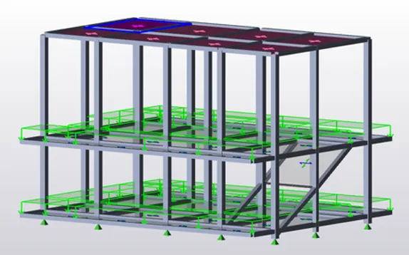
RESULT : Therefore live load has been calculated in design report and dead load has been applied
3. Generate manual wind loading in the design report based IS code as per the following input
- Basic wind speed = 50m/s
- Terrain category 2
AIM : To generate manual wind loading in the design report based on IS code as per the following inputs
TOOLS REQUIRE : Dimensions, Microsoft excel
PROCEDURE :
- Firstly open the model for which wind load to be applied
- Now take the required dimensions of the model such as height, length, width etc
- Now place the values in the Microsoft Excel Worksheet accordingly
|
Wind load calculations as per IS: 875 P3-1987 |
||||||||||
|
Basic parameters |
||||||||||
|
Basic wind speed Vb= |
50 |
m/s |
Terrain category= |
2 |
||||||
|
Probable design life= |
50 |
years |
class of structure = |
A |
||||||
|
Greater horizontal dimension, l= |
19.25 |
m |
Ratio for wall and roof co-efficients: |
|||||||
|
Lesser horizontal dimension, w= |
13.33 |
m |
||||||||
|
Eaves level height = |
7.7 |
m |
wall = |
l/w = |
1.44 |
|||||
|
Width of frame-1, grid A and B |
7 |
m |
h/w = |
0.57 |
||||||
|
Roof = |
h/w = |
0.57 |
||||||||
|
Topography factor, k3= |
1 |
|||||||||
|
Risk co-efficient, k1= |
1 |
(for 50 years) |
||||||||
|
Height(m)= |
upto 10 |
|||||||||
|
Terrain factor & str.size factor k2= |
1 |
|||||||||
|
Important factor for cyclonic, k4= |
1 |
|||||||||
|
Design wind speed , Vz= Vb*k1*k2*k3*k4= |
50 |
|||||||||
|
Design wind pressure (N/m |
(N/m^2), Pz= 0.6*vz^2= |
1500 |
||||||||
|
Design wind speed(kN/m^2), Pz = |
1.5 |
|||||||||
|
Roof angle, α = |
0 |
degree |
||||||||
|
Internal pressure coefficient, α = |
0.5 |
(upto 20% openeing) () |
(Cl.6.2.3.3 IS 875 P3:1987) |
|||||||
|
Internal pressure coefficient, α = |
-0.5 |
(upto 20% openeing) () |
||||||||
|
Wall loading calculations : |
||||||||||
|
Wind direction : +Y |
||||||||||
|
Wind load along Y-Direction |
(Face A): |
_+ Cpi |
_- Cpi |
|||||||
|
Height at different level = |
upto 10 |
upto 10 |
||||||||
|
External pressure coefficient, Cpe = |
0.7 |
0.7 |
||||||||
|
Internal pressure coefficient, Cpi = |
0.5 |
-0.5 |
||||||||
|
Net pressure coefficient, Cp = |
0.2 |
1.2 |
||||||||
|
Design wind pressure for wall = |
1500 |
1500 |
||||||||
|
Loading to be applied on the wall = |
1.05 |
1.05 |
||||||||
|
factor ( loading * 1.05) = |
1.1 |
1.1 |
||||||||
|
Wind load along Y-Direction |
(face B): |
_+Cpi |
_-Cpi |
|||||||
|
Height at different level = |
upto 10 |
upto 10 |
||||||||
|
External pressure coefficient, Cpe = |
-0.25 |
-0.25 |
||||||||
|
Internal pressure coefficient, Cpi = |
0.5 |
-0.5 |
||||||||
|
Net pressure coefficient, Cp = |
-0.75 |
0.25 |
||||||||
|
Design wind pressure for wall = |
1.207 |
1.207 |
||||||||
|
Loading to be applied on the wall = |
-0.905 |
0.302 |
||||||||
|
factor ( loading * 1.05) = |
-0.95 |
0.32 |
||||||||
|
wind load along Y-Direction |
(Face C & D) |
_+Cpi |
_-Cpi |
|||||||
|
Height at different level = |
upto 10 |
upto 10 |
||||||||
|
External pressure coefficient, Cpe = |
-0.6 |
-0.6 |
||||||||
|
Internal pressure coefficient, Cpi = |
0.5 |
-0.5 |
||||||||
|
Net pressure coefficient, Cp = |
-1.1 |
-0.1 |
||||||||
|
Design wind pressure for wall = |
1.207 |
1.207 |
||||||||
|
Loading to be applied on the wall = |
-1.328 |
-0.12 |
||||||||
|
factor ( loading * 1.05) = |
-1.4 |
-0.13 |
||||||||
|
Roof loading calculations |
||||||||||
|
Wind direction -Y |
_+Cpi |
_-Cpi |
||||||||
|
h/w = 0.78 |
h/w = 0.78 |
|||||||||
|
External pressure coefficient, Cpe = |
-0.88 |
-0.4 |
-0.88 |
-0.4 |
||||||
|
Internal pressure coefficient, Cpi = |
0.5 |
0.5 |
-0.5 |
-0.5 |
||||||
|
Net pressure coefficient, Cp = |
-1.38 |
-0.9 |
-0.38 |
0.1 |
||||||
|
Design wind pressure for roof, Pz = |
1.207 |
1.207 |
1.207 |
1.207 |
||||||
|
Wind load along X-direction ( Roof EG): |
_+Cpi |
_-Cpi |
||||||||
|
Height at different level = |
upto 10 |
upto 10 |
||||||||
|
External pressure coefficient, Cpe = |
-0.76 |
-0.76 |
||||||||
|
Internal pressure coefficient, Cpi = |
0.5 |
-0.5 |
||||||||
|
Net pressure coefficient, Cp = |
-1.26 |
-0.26 |
||||||||
|
Design wind pressure for wall = |
1.207 |
1.207 |
||||||||
|
Loading to be applied on the wall = |
-1.52 |
-0.314 |
||||||||
|
factor ( loading * 1.05) = |
-1.596 |
-0.33 |
||||||||
|
Wind load along X- direction ( Roof FH) : |
_+Cpi |
_-Cpi |
||||||||
|
Height at different level = |
upto 10 |
upto 10 |
||||||||
|
External pressure coefficient, Cpe = |
0 |
0 |
||||||||
|
0.5 |
-0.5 |
||||||||
|
Net pressure coefficient, Cp = |
-0.5 |
0.5 |
||||||||
|
Design wind pressure for wall = |
1.207 |
1.207 |
||||||||
|
Loading to be applied on the wall = |
-0.6 |
0.6 |
||||||||
|
factor ( loading * 1.05) = |
-0.63 |
0.63 |
||||||||
RESULT : Therefore Manual wind loads are generated successfully
4. Based on the above calculation apply the loadings on the model.
AIM : To apply loadings on the model as per above calculations
TOOLS REQUIRE : Loads, load cases, properties browser
PROCEDURE :
- Firstly open previous model file
- Now select load cases option then a pop up window appears then add required load cases accordingly and name them
- Now select required load case from below tool bar located in project work space
- Then follow the same procedure for all the frames
- Now apply loads to roof level
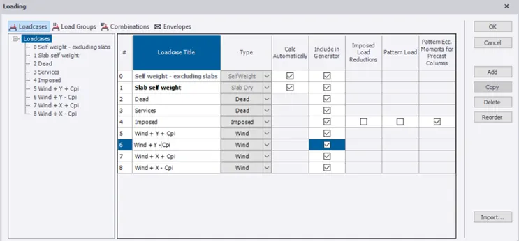
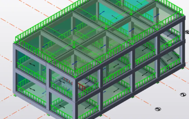
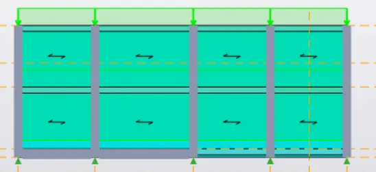
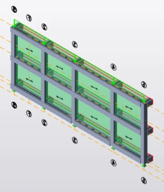
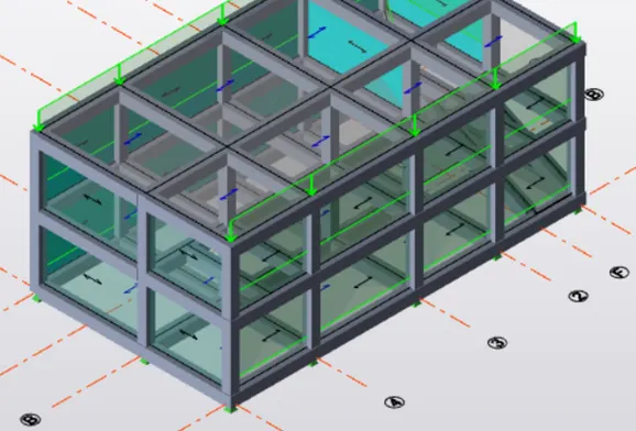
RESULT : Therefore based on above calculations loads are applied successfully