REVIT_Creation of Basic Drawing_Week 2
1Q) BIM is defined as “ Building Information and Modeling “. It is 3D model based software, which helps us to plan, design,manage building construction and visualize very efficiently by using wide variety of tools. BIM contains wide range of materials data when compared with CAD. Some best features of BIM include
- More Precise planning
- Best Visualization
- Access to all kinds of Information
2Q)
AIM : To select required elements from families and understanding the concept of categories, families, elements and instances in Revit.
TOOLS REQUIRE : Insert, load family, library, doors
PROCEDURE :
- Firstly draw a sample layout and select 3D view.
- Select Insert tool from the tool bar, then we can see load family option in insert tool panel.

- Click on load family, a pop up window appears, which consists of a wide range of elements.
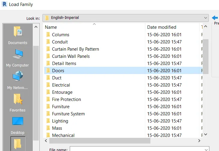
- Now select on required elements
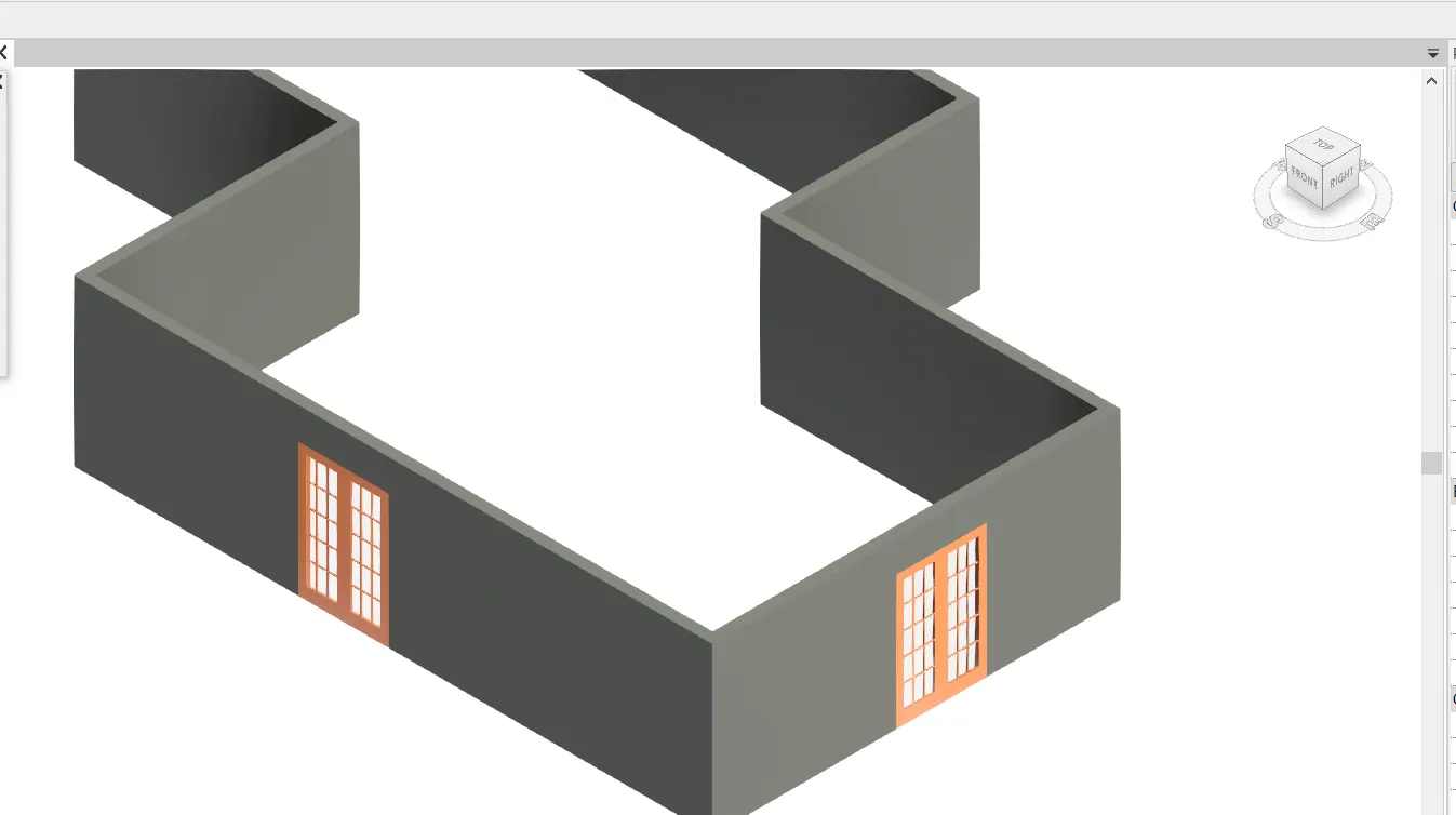
- After selecting the elements apply that element to the layout.
RESULT : Required family elements are used in the project successfully.
3Q)
AIM : To Open a new project file with architectural template and saving the with a name and to fill the details of the project and to create thee backups for the project.
TOOLS REQUIRE : file, save as, file name, options
PROCEDURE :
- Firstly after opening the Revit software, select new project.
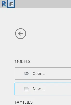
- After that a pop up window appears, select architectural template from it.
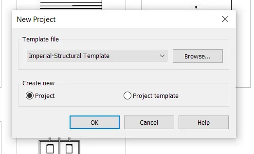
- Now select manage tool option, then we can see project information tool in it.

- Fill all the details of the project appropriately.
- Next save the new project, by selecting file tool and save as option.
- Then a pop up window appears, give a proper name to project and select options tool which is adjacent to naming bar.
- After selecting options a pop up window appears, now change no. of maximum backups into three.
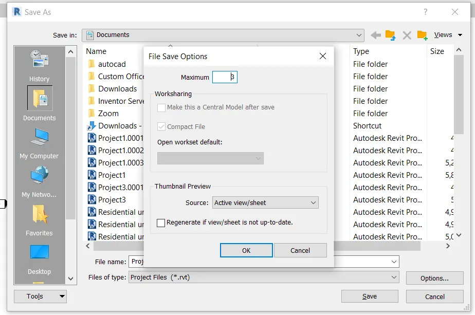
RESULT : By following above procedure I have created a new project, saved 3 back up files and entered the project information.
4Q) (a)
AIM : To understand the concept of Levels and Grids. And to create following levels
Ground Floor @ 0’
First Floor @ 10’
Second Floor @ 20’
Roof @ 30’
TOOLS REQUIRE : Architecture tool, project browser, Elevations, Levels
PROCEDURE :
- Firstly draw a layout by using wall tool from architectural tool.
- After that select west elevation from project browser, we can see ground floor level and first floor levels of our layout.
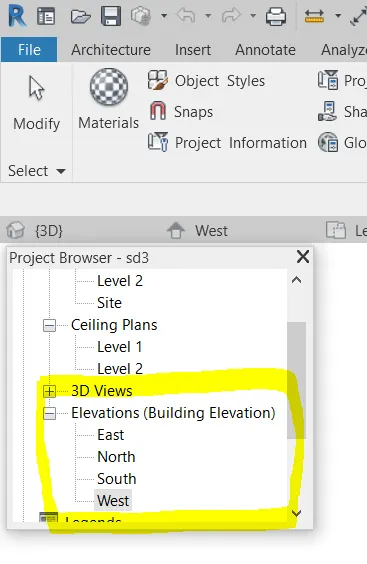
- For second floor and roof levels draw the layouts in respective plan and then add on levels.
- Now select level tool and add required no. of levels to the layout.

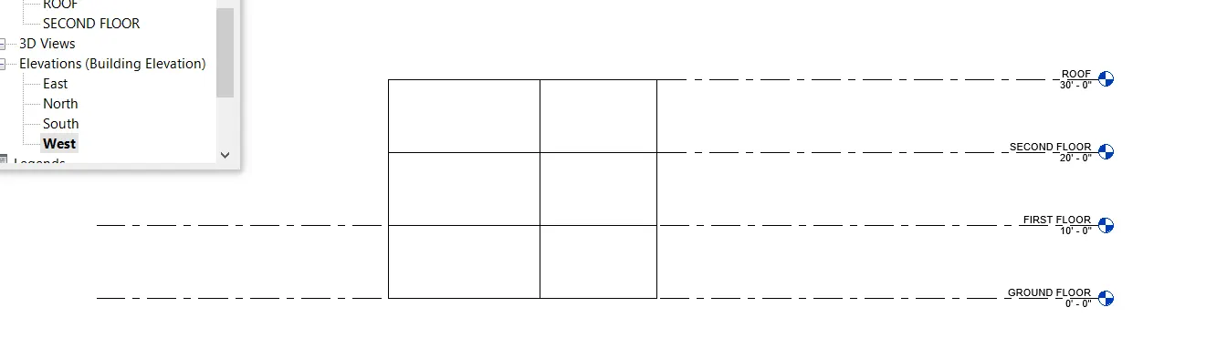
RESULT : With this i understood how to add on levels in the project.
(b)
AIM : To create grids
- Transverse grids A,B,C,D,E @ 10’ Spacing
- Longitudinal grids 1 to 10 @20’ Spacing
TOOLS REQUIRE : Architecture tool, elevation, grid
PROCEDURE :
- Firstly draw a layout by using wall tool from architectural tool.
- After that select west elevation from project browser, and then select grid tool.
- Now select grid tool and draw the grids
- Firstly draw transverse grids A,B,C,D,E with 10’ spacing and then draw longitudinal grids 1 to 10 with 20’ spacing.
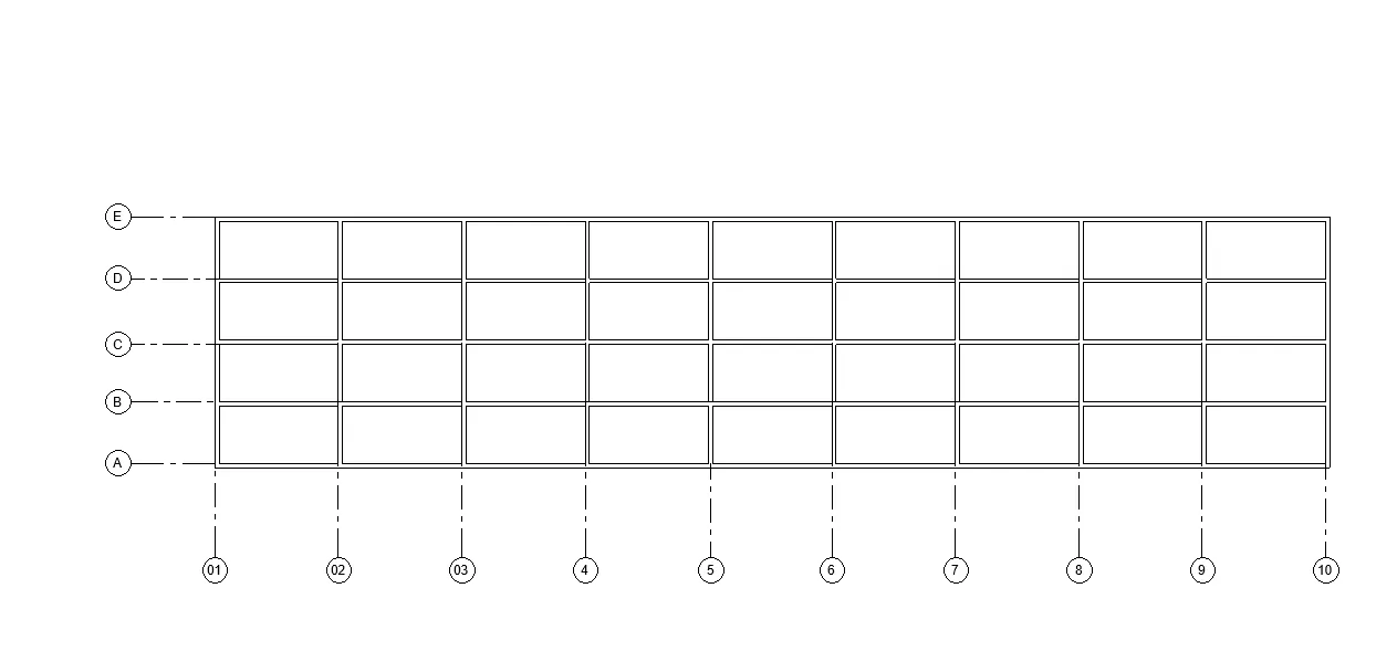
RESULT : Required grids are drawn using grid tool.
5Q)
AIM : To draw the 3D model of residential unit.
TOOLS REQUIRE : Architectural template, architecture tool, project browser, 3d view
PROCEDURE :
- Firstly select architectural template.
- Select architecture tool and then select wall tool and draw a layout.
- After drawing the layout select load families and select required doors and windows.
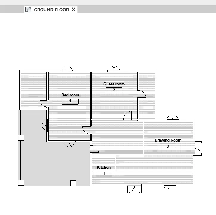
- Place all doors and windows at required places.
- Now select 3D view from project browser bar.
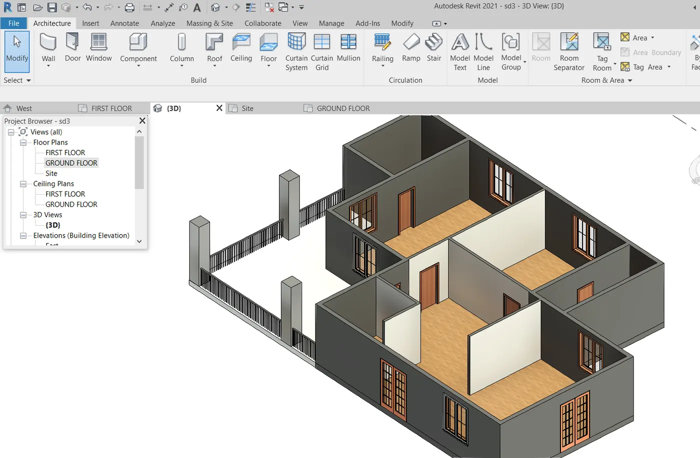
RESULT : Above picture show the 3D view of selected layout.
6Q)
AIM : To include dimensions of rooms, components in the residential unit.
TOOLS REQUIRE : Architecture tool, annotate tool, room tag, load family tool
PROCEDURE :
- Firstly draw the layout of the residential unit, wall tool from architecture tool bar.
- And then select room tag and tag every room and change accordingly to the plan.
- Then select load families and select required doors and windows for the residential unit.
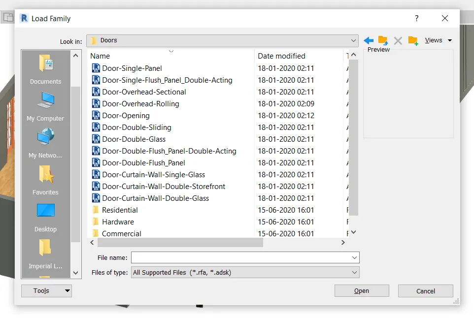
- Now select on components tool then a pop up window appears, from that select edit type option, which is located in project browser, then load new required components, to include them in the layout.
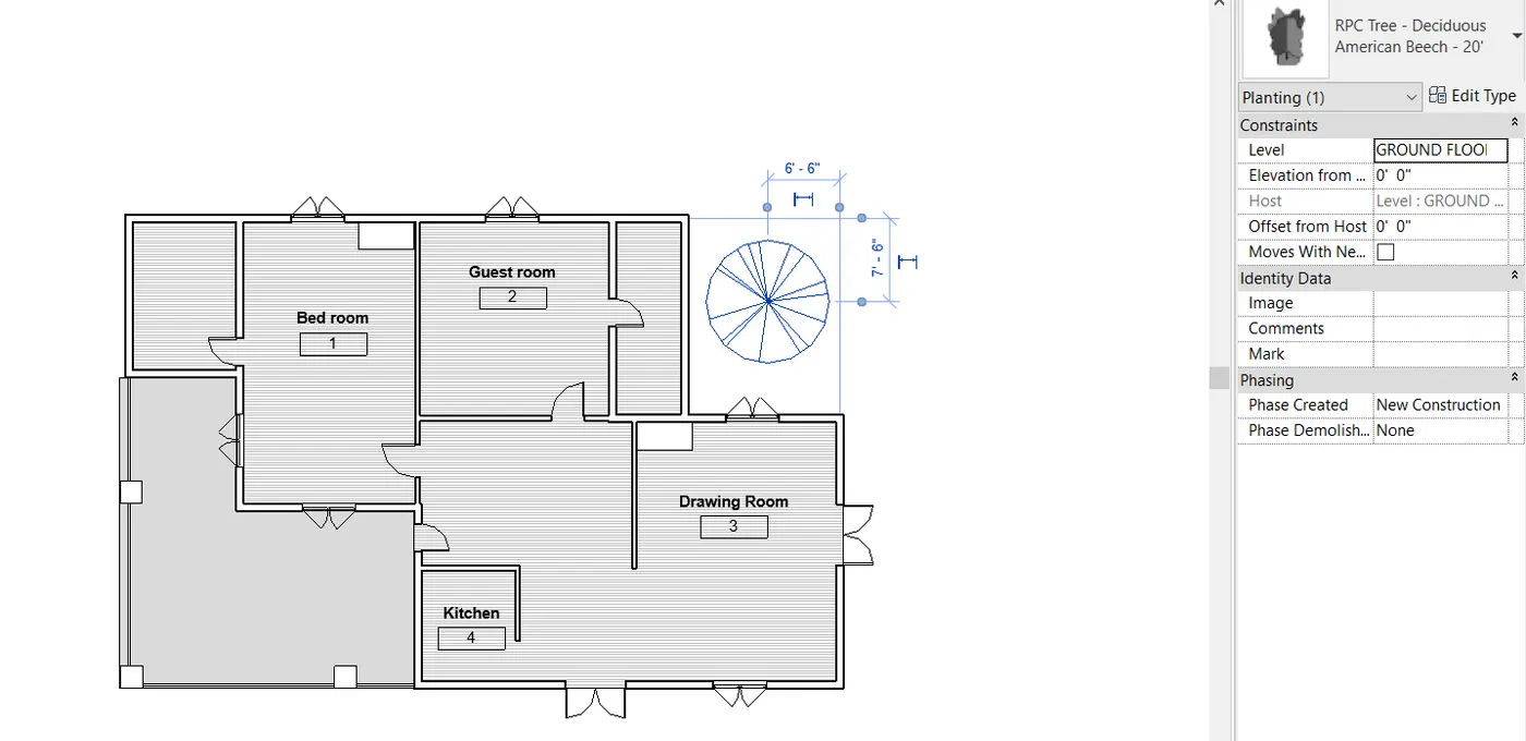
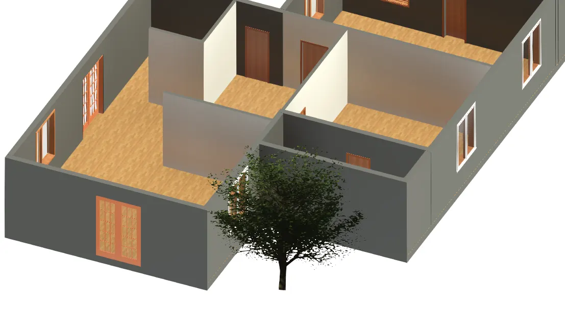
- After inserting all the required components, select annotate tool then select aligned option to give required dimensions to the rooms.
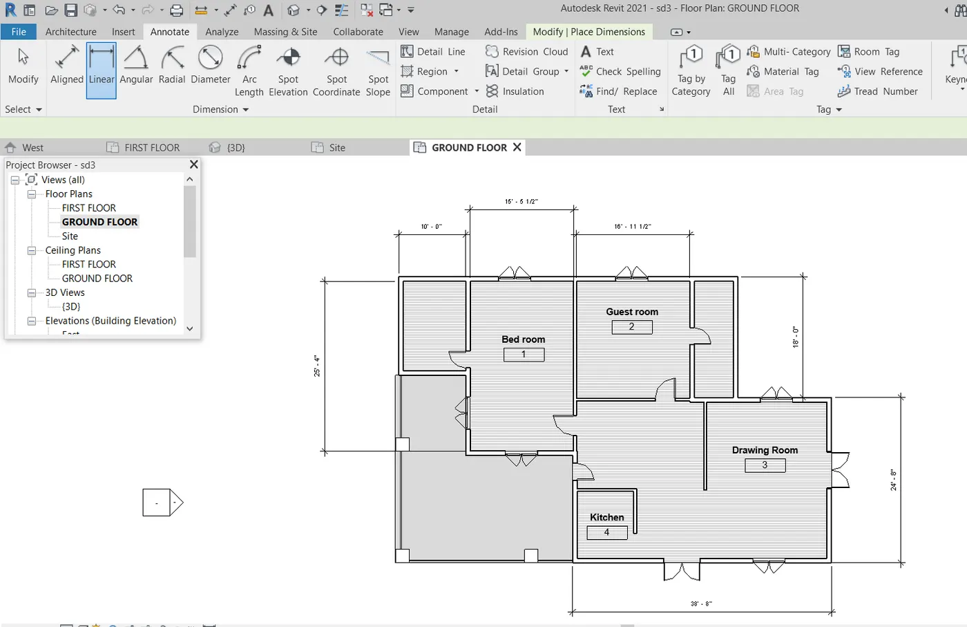
RESULT : The given task of including dimensions of rooms, components in the residential unit are executed.
7Q)
AIM : To insert Doors, Windows, Tables, Chair, Couch, Bed, Lamps from the library in a residential unit.
TOOLS REQUIRE : Insert, load families, components
PROCEDURE :
- Firstly select insert tool and then select load family option from it.
- Then select required elements to be used in residential unit.
- After selecting click on architecture tool and select components.
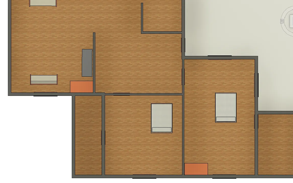
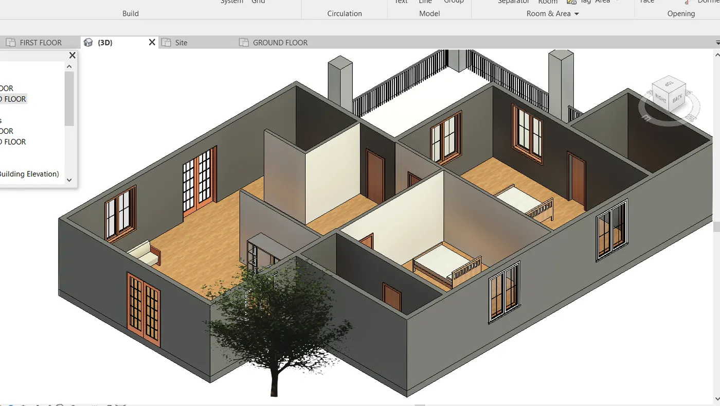
- Then place all the required components which are loaded from families in the residential unit.
- Adjust them according to the layout.
RESULT : All components are inserted successfully.