Week 8 - Challenge 1 - Draft Analysis on a Fan Cover
AIM:-
To Create the tooling axis for the given Fan cover model meeting the requirements of the draft angle and perform the Draft analysis on the model.
OBJECTIVE:-
The main objection is to perform draft analysis to check if the part has the given draft in its all face and to determine the tooling axis.
Draft angle Recommendation:
1. 3 degree is a nominal draft.
2. 0.5 is a minimum draft that increases the cost of manufacturing.
3. 7 degrees for textured faces.
Procedure for Draft Axis
- Check the connectivity to the Class A surface model.
- Defining point as Circle point type.
- Create a dummy axis tool at the point in the Z direction.
- Create Axis system at point 1.
- Intersect the model ZX of Axis System 1.
- Create two point-to-point lines which inclined towards the dummy axis tool.
- Create Bisecting line with reference of two lines and point 1.
- Edit line color and thickness and assume as X tooling Axis.
- Intersect the model with YZ of Axis System 1.
- Create two point-to-point lines which inclined towards the dummy axis tool.
- Create Bisecting line with reference of two lines and point 1.
- Edit the color and thickness and assume as Y tooling Axis.
- Create Bisecting line with reference of X tooling axis, and point 1 for Main tooling Axis.
- Publication Main tooling and Class A surface model of Fan Cover.
- Select View mode and select material as shading.
- Lastly, select Feature Draft Analysis and procedure.
Methodology for finding Draft Axis and the Draft Analysis
- Connectivity Check
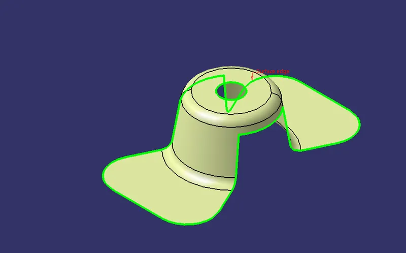
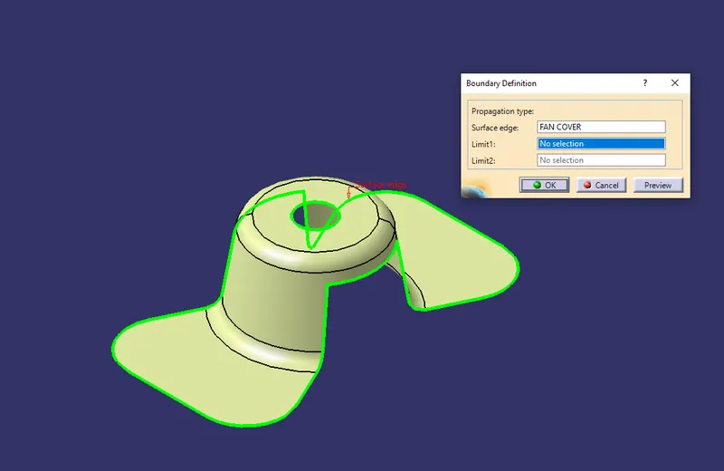
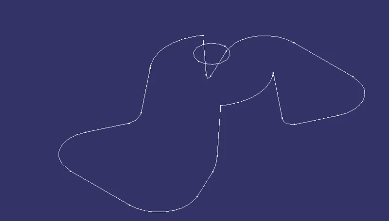
Firstly, we have to check the continuity of the given class A surface to ensure the Class A surface is properly joined or no discontinuity is present, this can be done using the join or boundary command in CATIA. Visual representation is shown below
- Dummy Tooling Axis
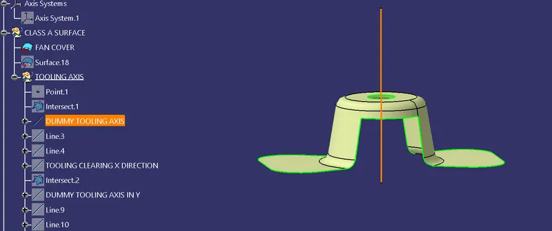
To create a dummy tool axis, create a line with points 1 and X- direction
- Creation of Tooling Axis
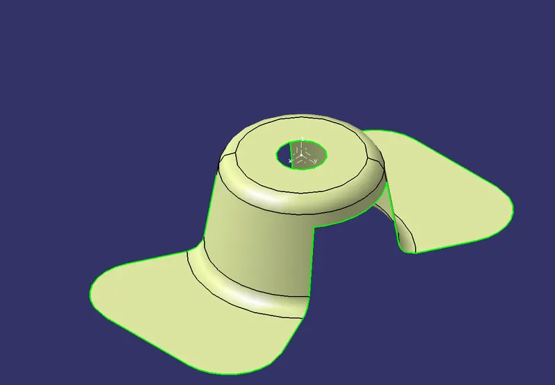
The tooling axis is used in the draft analysis, it is important to select the right axis for tooling considering the ejection of part from the mold, the next step is to decide the tooling axis direction. The tooling axis direction in which mold or core & cavity opens. Visual representation is shown below.
- Finding X Tooling Axis
To find the X tooling axis select the intersect option, select the ZX plane of the Axis system as the first element, and fan cover (Class A surface)
As the second element. This will give a 2D sketch of the fan cover viewing from X-Direction.
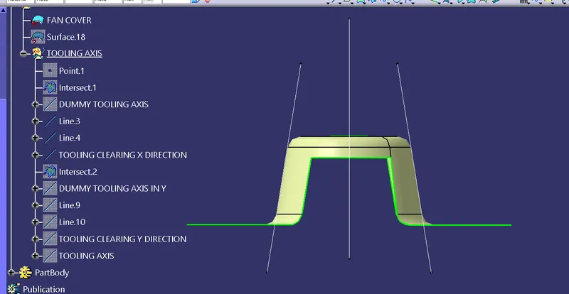
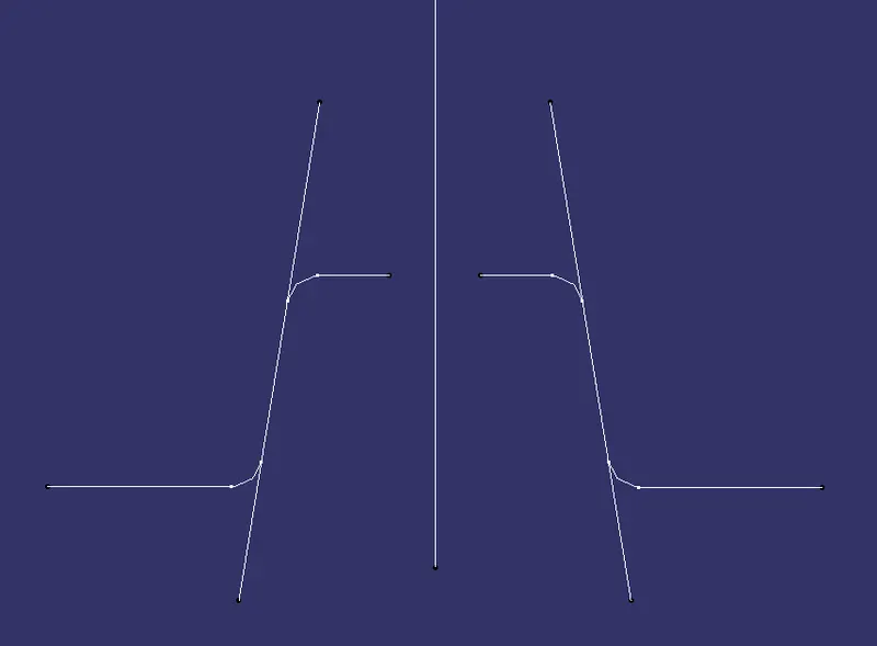
Now create lines representing the walls of the fan cover using the point-to-point option with the help of intersecting. Using these 2 lines, create the tooling axis clearing X direction. Create a line that bisects these two lines from a reference point in the Z direction. Visual Representation showed below of X- Tooling Axis
- Finding Y Tooling Axis
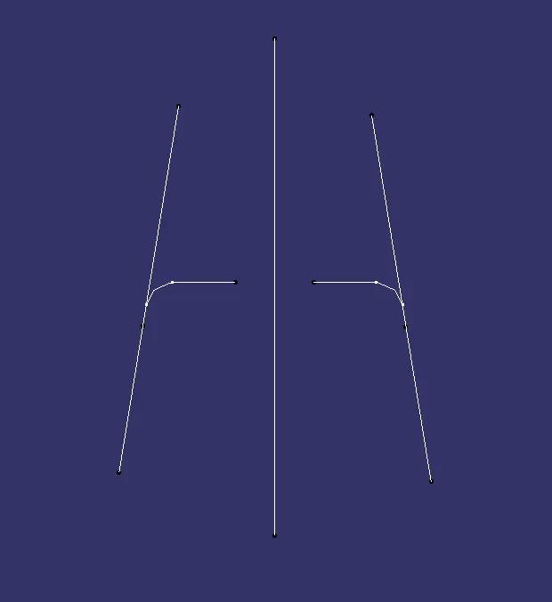
To find the Y tooling axis select the intersect option, select the YZ plane of the Axis system as the first element, and fan cover (Class A surface) As the second element. This will give a 2D sketch of the fan cover viewing from Y-Direction.
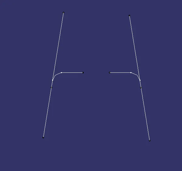
Now create lines representing the walls of the fan cover using the point-to-point option with the help of intersecting. Using these 2 lines, create the tooling axis clearing Y direction. Create a line that bisects these two lines from a reference point in the Z direction. Visual Representation is shown below of X- Tooling Axis
- Finding Main Draft Tooling Axis
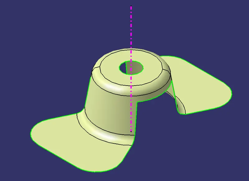
To find the main tooling axis, create a line using bisecting option and select the “X” tooling axis as line 1, “Y” tooling axis as line 2, and Point 1 as a Reference point, Select the bisected line and change color and thickness. Visual Representation is shown below.

7. PUBLICATION:-
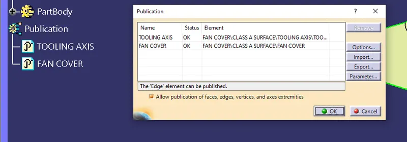
To make sure that the tooling axis and CAT is clearly visible.
8. Feature Draft Analysis
- Before performing the draft analysis, we create the Main tooling axis then the procedure.
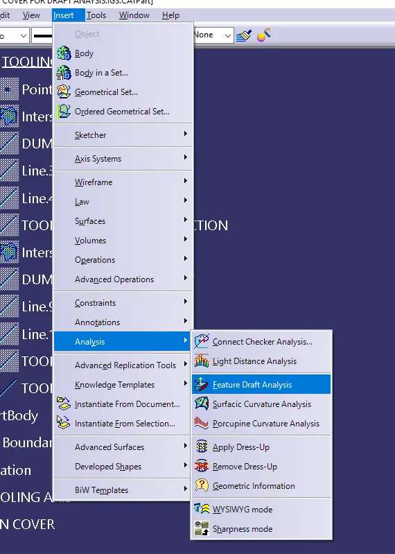
- {Go to menu bar > select insert > Analysis> Feature Draft Analysis}.
- Now, align the compass Z-Direction with the main tooling axis which we created in the previous steps.
- Now, open the color scale and enter the value as 3 deg.
- Now, check if every face has an angle greater than the given angle.
- Also, if the whole body is in green color, it means that the value at all faces is greater than the provided angle
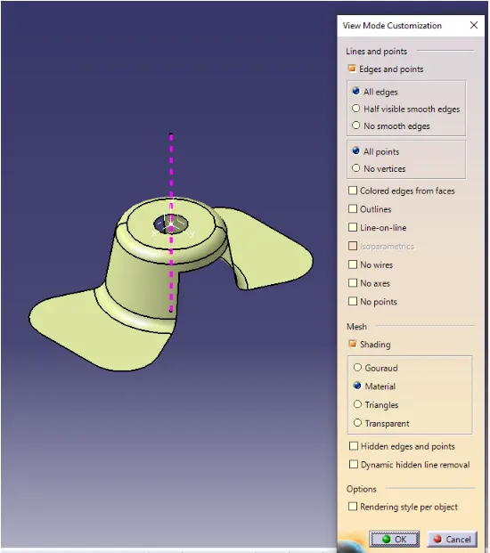
After selecting the draft analysis we get these two dialogue boxes in the first row, two modes are displayed
the second row is displayed and the third is direction, using their modes we can use drafting angles at the maximum and the minimum angles
the display is done using background light analysis in the direction we can use the direction axis and lock it.
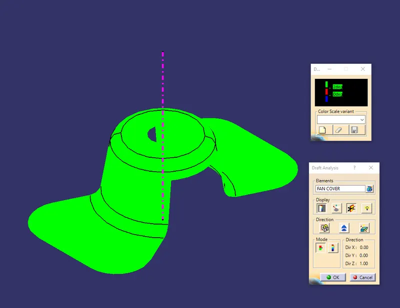
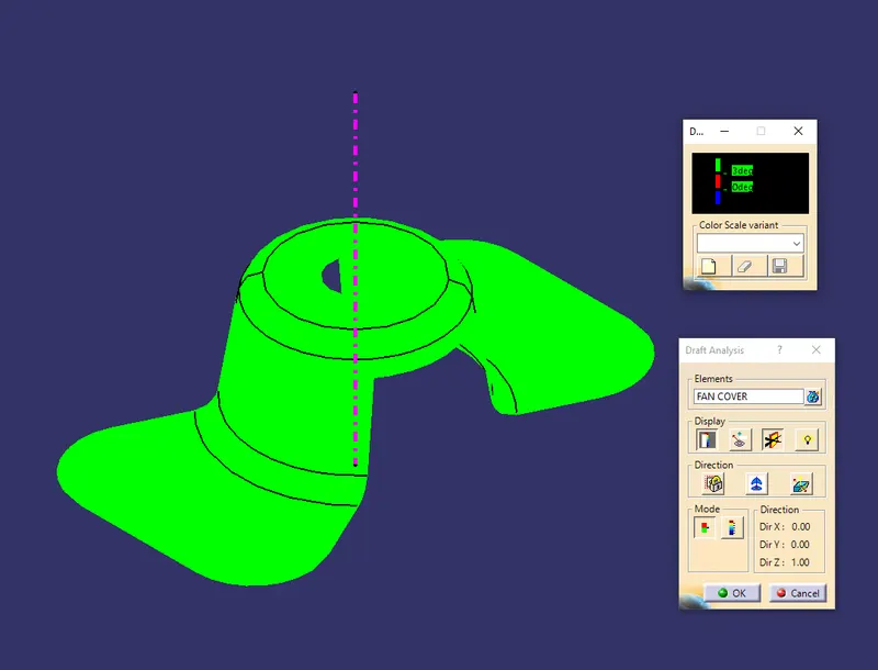
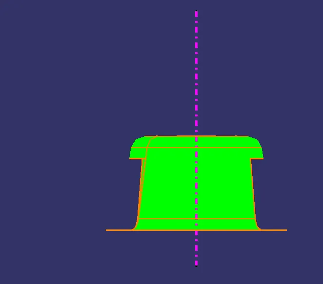
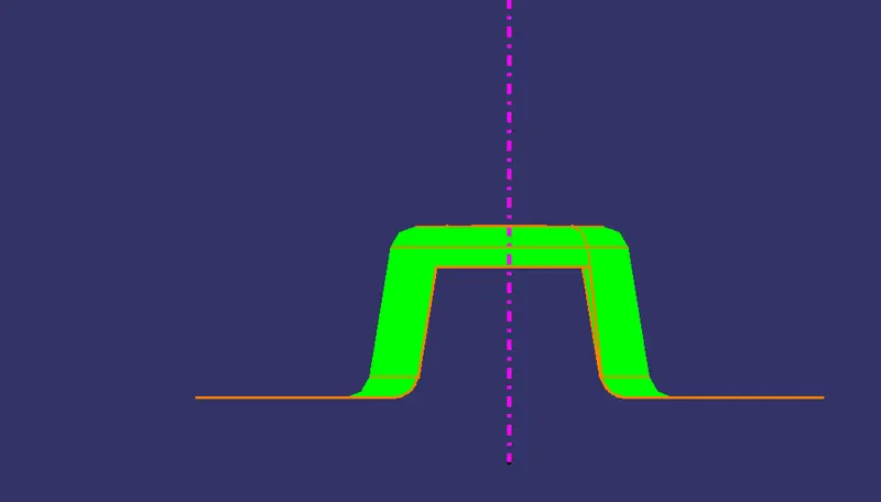
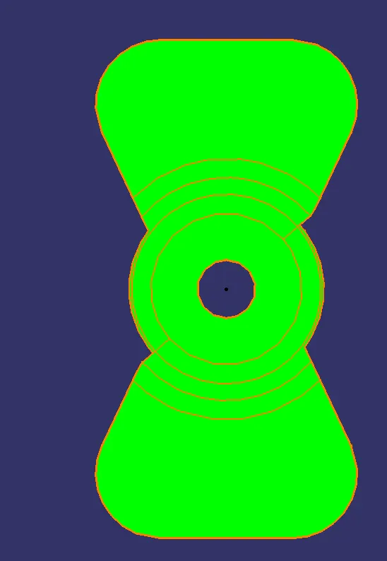
THE 3 DEGREE DRAFT ANGLE IS POSITIVE FOR MODELLING THE OBJECT.
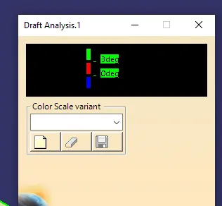
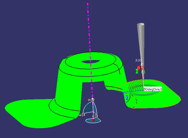
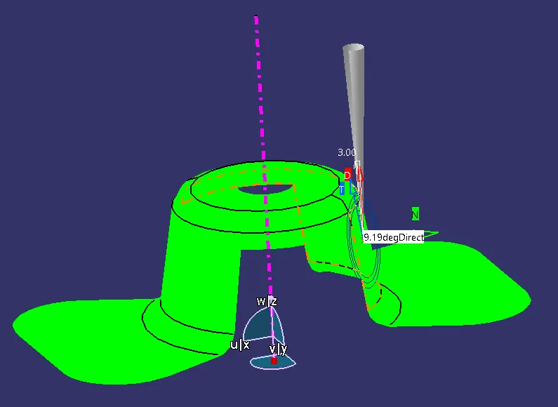
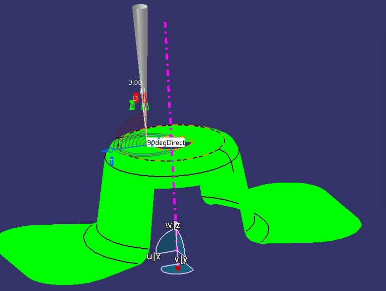
At each and every fan cover place, we get the angle, at each position.
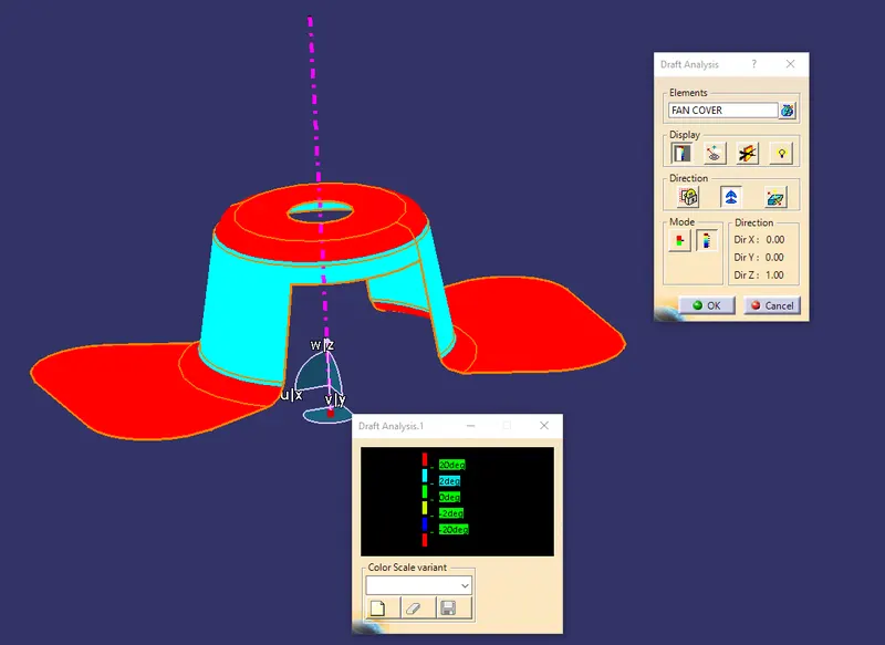
THE RED COLOUR IS DISPLAYED AS WHERE THE DRAFTING IS NOT POSSIBLE
DRAFT IN VARIOUS VIEWS:-
FRONT VIEW:-
SIDE VIEW:-
TOP VIEW:-
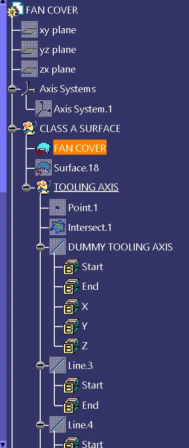
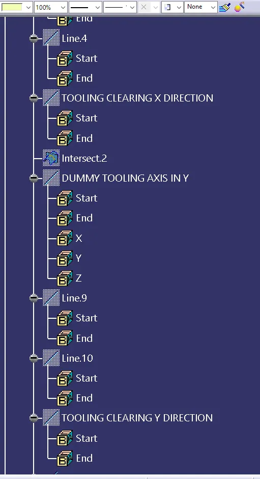
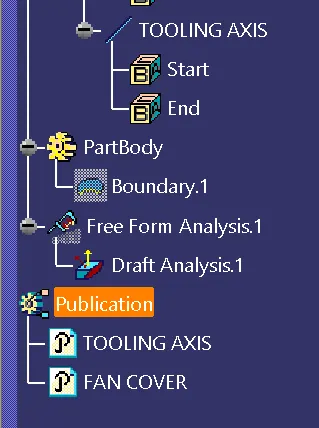
TREE STRUCTURE:-
CONCLUSION :
The draft analysis of fan cover with the help of CATIA and