Week -2
AIM:-
To make a simulink model of Doorbell using solenoid block.
SITUATION:-
Create a situation where the switch is closed for 2 seconds and then released. Observe the physical movement of the plunger.
BLOCKS USED IN THE MODEL:-
- Pulse generator
- Scope
- Battery
- Solenoid
- Simulink-PS converter
- Electrical plain switch
- Electrical reference
- Ideal Translational motion sensor
- Solver configuration
- Mechanical Translational reference
SIMULINK MODEL:-
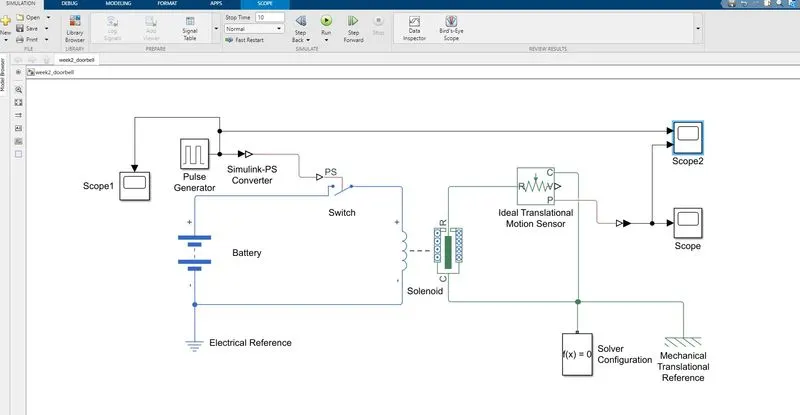
SIMULINK MODEL EXPLANATION:-
The pulse generator is used to create the pulse at a regular interval. When the defined parameters cross the threshold the switch will close otherwise it will remain open
- We created the situation where the switch is closed for 2 seconds and then released.
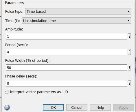
- As we see in the above image we feed the parameters to the system and the output will be in that manner. As we want the system to be closed for 2 seconds and then open for 2 seconds so we feed the data in the time period value as 4 secs.
- As the total time period is 4 sec so our pulse width must be 50% and then applied the changes
- Solenoid block is used in the system as when the circuit will close there will be the magnetic repulsion occur in the solenoid block and the plunger moves away and will create the vibrations. And the result will occur in the scope.
- The battery is used to give the electrical input and when it comes to the solenoid block we get the mechanical output.
- The switch box used is controlled by an external physical signal when the external signal is greater than the threshold parameters then the switch will close otherwise it will remain open.
- One terminal of the switch box is connected to the positive terminal of the battery and another terminal is connected to the solenoid block further to the negative terminal of the battery and that completes the circuit.
- Electrical reference is connected to the circuit which is very essential without it the circuit will not be complete.
- The one end of the Simulink-PS converter is connected to the switch and other end is connected to the pulse generator.
- Port R of the ideal translational motion sensor is connected to the solenoid block to observe the translational motion that is going to occur in the solenoid. Port C is connected to the mechanical reference.
- Port P is connected to the Simulink-PS converter and further, it is connected to the scope to give the output.
- Mechanical translational reference is connected to complete the circuit.
- Solver Configuration is needed because each physical network represented by a connected simscape block requires solver setting information for simulation.
SCOPE OUTPUT:-
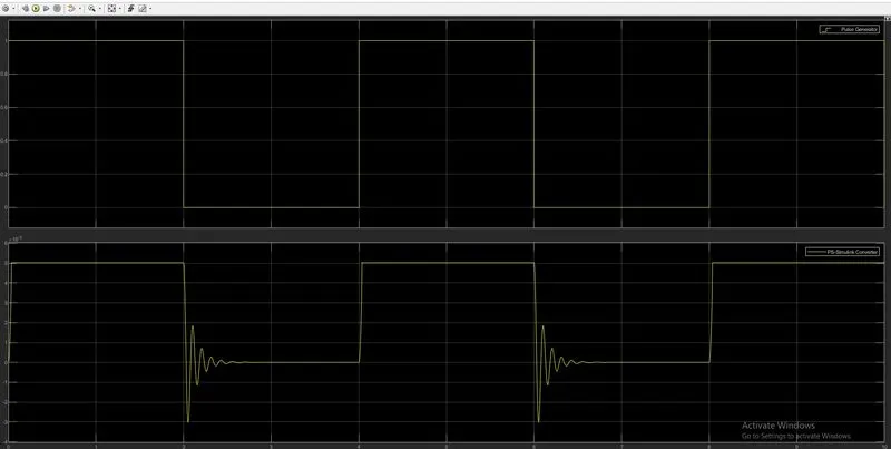
The above image shows the pulse pattern given as input also the pulse pattern given as output.
As we want circuit closed only for 2 seconds and then it will open. When the circuit will close then the solenoid will generate the vibration. As the less the damping frequency the more it will generate the vibrations and vise versa.
CONCLUSION:-
We created the Simulink model of doorbell using Simulink and create a situation where the circuit is closed for 2 sec and then released.
PART 2:-
AIM:-
To use the Thermistor to sense the temperature of a heater and turn on and turn off the fan.
SITUATION:-
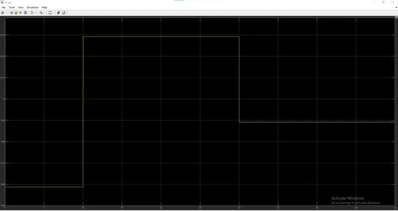
Temperature source: 20 °C from 0 to 10 seconds, 27 °C from 10 to 30 seconds, 23 °C from 30 to 50 seconds
Fan conditions: ON if the temperature is above 25 °C, OFF otherwise.
BLOCKS USED IN THIS MODEL:-
- Signal Builder
- Temperature source
- Simulink-PS convertor
- Controlled Temperature source
- Thermistor
- Resistor
- Voltage sensor
- Battery
- Electrical Reference
- PS-Simulink converter
- Constant
- Slover Configuration
- Switch from HDL
- Scope
SIMULINK MODEL:-
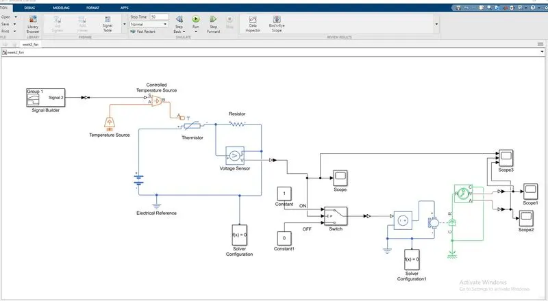
SIMULINK MODEL EXPLANATION:-
- As we can see in the model there is signal builder is connected with the Simulink-PS convertor.
- The work of signal builders is to provide a variable input signal to the system. And it will form the wave with respect to that input only.
- As in this example, we put the input data for time values as [0 10 10 30 30 50] and for Y values we put [293 293 300 300 296 296] according to that we only get the graph.
- After the Simulink-PS converter we used a Controlled temperature source, there are 3 ports to this block S port is connected with the Simulink-PS convertor where we are providing the conditions to the port related to that it will then show the output. A port that is connected to a temperature source is an ideal energy source in a thermal network that can maintain a constant absolute temperature at the port regardless of the heat flow rate.
- Port B is the output port that is connected to port A of the thermistor. Controlled temperature source which will provide the required temperature according to signal provided to its A port.
- Then the Thermistor comes into action where the thermistor has a resistance capacity more than the conducting material and less than insulating material. Its electrical resistance varies with the change in temperature or thermally sensitive resistor.
- Thermistor has 2 ports +ve and -ve terminals which are connected to the battery, besides thermistor resistor is connected in series which is used to provide opposing current in a circuit.
- A voltage sensor is used to measure voltage or potential differences across any electrical device. And it must connect in parallel to give the proper output.
- Then we have to use a PS-Simulink converter in order to connect the Simulink block.
- Then we used a Switch block which has three ports this block is used from the library Simulink / signal routing where it has named three ports port 1, port 2, and port 3. Port 1 and port 3 are connected with the constant block wherein the constant block 1, we used 1 as a switch ON and Another constant block is used for the OFF condition where the value is 0.
- Port 2 is the control input where the signal given to port 2 is satisfied with the condition and it is satisfied with the condition and threshold of the switch block and then it passes to port 1 as an output and if it is not satisfied it will pass through the port 3 as an output.
- The scope is connected to port 2 which shows the output signal with respect to time in an X-axis.
- To the output of the switch block, we used a Simulink-PS converter which is further connected to the controlled voltage source from the library Simulink/ electrical near Voltage-Controlled Voltage Source (VCVS). The voltage source output voltage is given by V = K*(V(+)-V(-)), where V(+) and V(-) are the voltages presented at the + and - control ports. Parameter K is the voltage gain.
- With the controlled voltage source we connected the DC motor block which uses the electrical input and converts it into mechanical output. We completed the electrical circuit by connecting the p+ve and - ve terminals with that circuit to connect the electrical reference and solver configuration to complete the circuit.
- On the mechanical side of the DC motor which will act as the fan motor, it will rotate with the maximum given rpm whenever the circuit gets closed and it and also when the condition gets satisfied the fan gets turned on.
- With the C port, we connect the rotational reference and to the R port, Ideal rotational motion sensor is connected which observes the rotational motion of the motor.
- The C port of the Ideal rotational motion sensor is connected with the mechanical rotational reference
-
Ideal rotational motion sensor block measures angular velocity or angle in a mechanical rotational network. The sensor is ideal since it does not account for inertia, friction, delays, energy consumption, and so on. The physical signal ports W and A report the angular velocity and angle, respectively, of port R relative to port C. The measured angular velocity is positive when the angular velocity at port R is greater than the angular velocity at port C.
- Then after measuring the output signal we used a scope with the PS- Simulink converter which is connected to port W and port A of the Ideal rotational motion sensor.
INPUT PARAMETERS WAVEFORM:-
OUTPUT:-
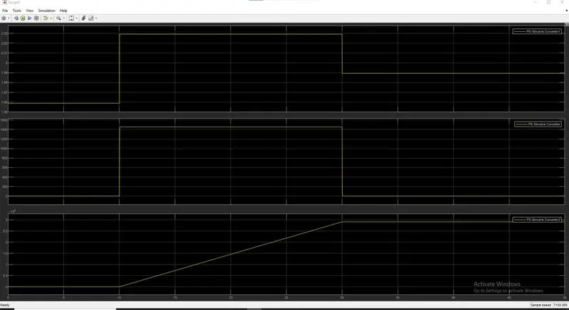
As we see in the graph for the first 0 to 10 seconds there is no output which means the circuit is not closed because the condition is not satisfied. Because the temperature did not raised to the threshold temperature which is 25°C. What happened in the first 0 to 10 seconds is when we ran the simulation the signal passed through the circuit as the temperature was 20°C for that period so the output signal goes to the switch box and it passed the output signal to the 0 constant boxes which are used for OFF condition so the fan will not turn on.
In the next 10 to30 sec time period temperature raised to 27°C which is more than 25°C which is the threshold temperature so what happened here in the switch box the port 2 is the control port where we gave the threshold parameter. Now as the temperature raised the threshold parameter the control port gives the signal to the ON constant ox that is 1 for ON condition. Then it will turn ON the fan.
As we see in the third graph the rpm of the motor is rising as now the circuit is closed.