Project
AIM:-
To Carry out a system-level simulation of an all-terrain vehicle and to prepare a technical report explaining the model properties and their results.
OBJECTIVE:-
Carry out a system-level simulation of an all-terrain vehicle. Prepare a technical report explaining the model properties & comments on the results.
All-terrain vehicle:-
An all-terrain vehicle (ATV) is defined as a motorized off-highway vehicle designed to travel on four low-pressure or non-pneumatic tires, having a seat designed to be straddled by the operator and handlebars for steering control. ATVs are subdivided into two types as designated by the manufacturer.
STUDY 1:-
Case 1:-
Simulink model of BAJA ATV with CVT:-
Without Dashboard
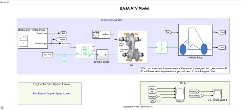
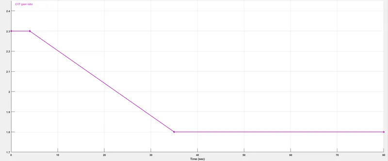
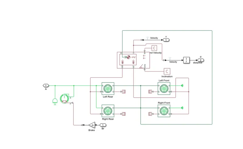
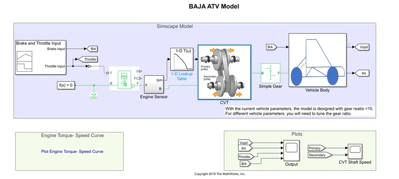
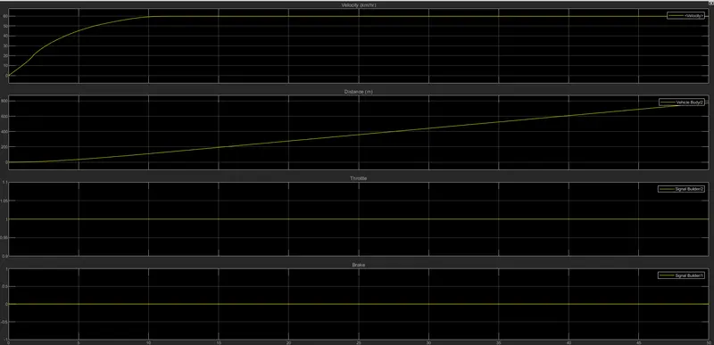
In the above image, we see the Simscape model of BAJA ATV where we used the signal builder block where we have given the CVT ratio to the signal builder as 2.3 and 1.8. This is the CVT ratio to the continuous variable transmission here we are giving some random values to the CVT ratio we are checking the vehicle performance.
Generic Engine:-
This block represents a system-level model of spark-ignition and diesel engines suitable for use at the initial stages of modeling when only the basic parameters are available. Optional idle speed and red line controllers are included.
The throttle input signal T lies between zero and one specifies the torque demanded from the engine as a fraction of the maximum possible torque. If the engine speed falls below the stall speed, the engine torque is blended to zero. If the engine speed exceeds the maximum speed, the simulation stops and issues an error message
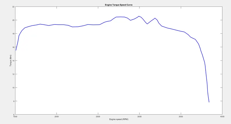
We have fed the data from the image by using the GRABIT command to our model from the engine torque-speed curve we feed the torque and the speed is 3840 rpm.
Continuous variable transmission (CVT):-
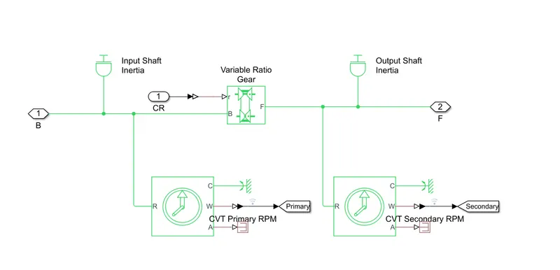
It consists of
- Primary pulley
- Variator
- Secondary pulley
- Belt
So the variator which is connected to the primary pulley when it goes outwards, the variator of the secondary pulley goes inward
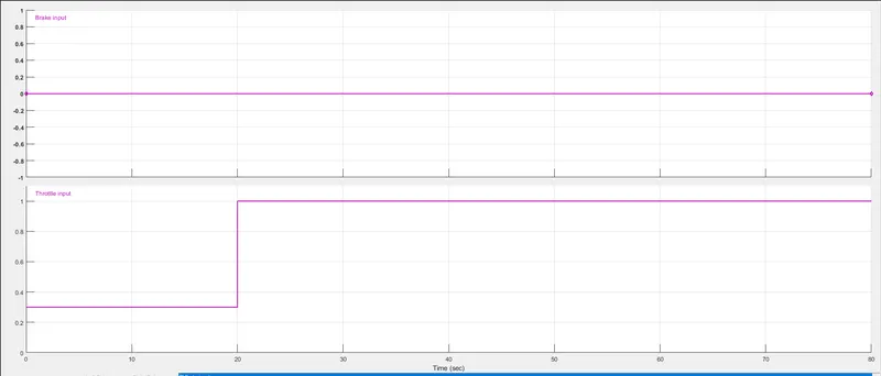
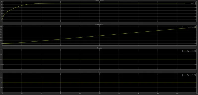
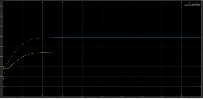
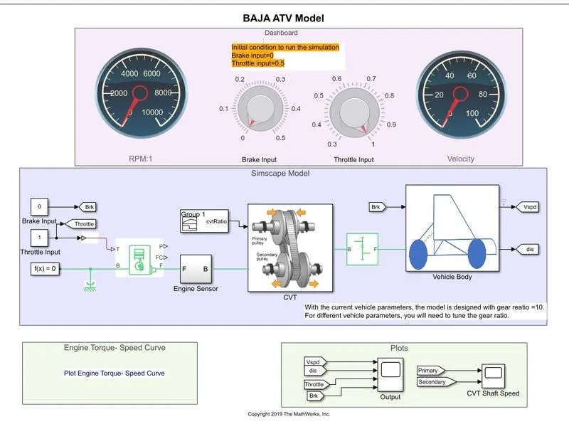
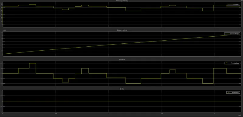
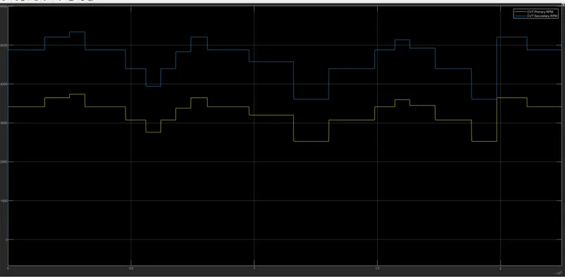
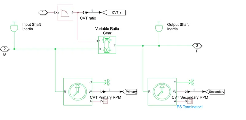
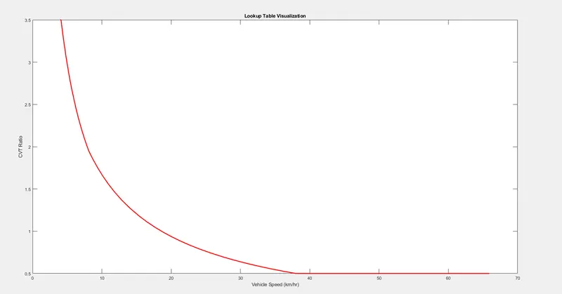
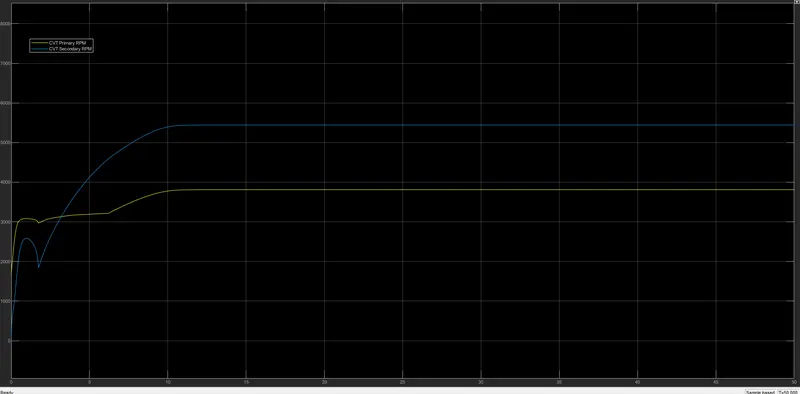
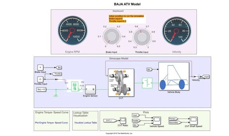
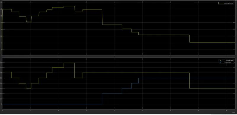
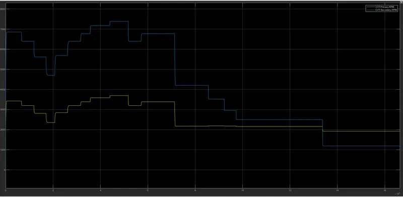
So Rp and when the variator is connected secondary pulley when it goes inwards, the variator of the primary pulley goes inwards It became Rp>Rs which leads to overdrive. Inside CVT we have input shaft inertia and output shaft inertia, which is representing the primary and secondary pulley. To specify the gear ratio we have a variable gear ratio block. Then with that, there is a primary and secondary RPM sensor. Simple Gear Ratio:- To connect the engine and CVT we need some speed reduction that is the reason we are using a simple gear ratio. It is just the mechanical system used to set the gear ratio we are taking it as 4 . Because it is working fine and it is making the engine work to its fullest. With that gear ratio, we go quickly over rpm. Vehicle Body:- In this block you can specify your car's mass number of wheels per axle, Horizontal distance from CG to the front axle, horizontal distance from CG to the rear axle, CG height above the ground we can also include the drag here. Here the data feed is simple we can feed the data on a practical based to get a better simulation of our own Baja model. Signal builder input:- For Brake and throttle For CVT Gear Ratio input:- Torque Vs Engine speed input:- Vehicle Body:- Output Case 1:- Vehicle speed:- It is clear from the graph that the vehicle attained its maximum speed v=55kmph at full throttle= 1 after 30 seconds then remain constant. The brake input is zero therefore there is no effect on the vehicle speed. CVT Shaft RPM:- This graph has been shown that the variation in angular velocities of input and output shafts of the variable gear transmission system. These values differ with respect to the gear ratio. Study 1 Case 2:- Simulink model for BAJA ATV using CVT with Dashboard:- In this model, we used knobs instead of signal builder blocks and these kh=nobs are connected with the circular gauge to show the rpm and velocity of the model. The brake input is starting from 0 to 0.5 and for the throttle input the initial and final range is 0.3 to 1 Output For CASE 2:- Vehicle speed:- As we can see in the output when we run our simulation for inf. time we can vary the throttle input with respect to that we get the speed. When throttle value is 0.5 and brake input is 0. When we increase the value of breaking then the velocity will decrease. CVT Shaft rpm:- STUDY2 Case 1:- Simulink model for BAJA ATV with CVT using lookup table:- CVT Block:- The only difference between this model and the previously studied model is we added a lookup table instead of using a signal builder block we provided the gear ratio input by using a lookup table. The vehicle velocity and shaft rpm are the same as before. Lookup Table Visualisation:- Output Case 1:- Vehicle Speed:- CVT Shaft rpm:- Both results are the same as that of the first case since the input parameters are the same we just implemented the lookup table instead of the signal builder. Study 2:- Case 2:- Simulink model for BAJA ATV with CVT using lookup table and dashboard:- We were using some random values to the CVT in study 1 and we were checking the vehicle speed and it is not realistic because the CVT ratio is depending upon the vehicle velocity. So then we used this model which is a close-loop model which has been built using the LOOKUP table. There is feedback coming from velocity if you go inside the CVT block there is a lookup table so based on the data given to the lookup table it is calculating the required amount of CVT ratio. And we are controlling throttle and brake input with the knobs. Output for case2:- VEHICLE SPEED:- This is similar to the CVT dashboard case. The variation in the vehicle velocity can be observed when we change or increase the throttle input. The velocity will increase and if we decrease the throttle input and increase the breaking input the velocity of the vehicle will decrease the reduction of speed will occur. And vehicle will stop if the breaking input is high. CVT Shaft RPM:- This graph indicates the variation in rpm of primary and secondary shafts with respect to input parameters. Conclusion:- Thus we have analyzed 4 different cases of BAJA ATV With CVT the vehicle velocity and shaft rpm with respect to variation in throttle input and brake input.