Week 8 - Challenge 1 - Draft Analysis on a Fan Cover
DRAFT ANALYSIS ON A FAN COVER
The main objective is to create a tooling axis for a given fan cover by satisfying the construction of surfaces and to perform draft analysis to check if the part has given draft to the surfaces which are lying parallel to the tooling axis.
DRAFT :
In engineering, draft is the amount of taper given to the surface of molded or cast parts perpendicular to the parting line.
The in build draft analysis tool used in CATIA to ensure that the faces are taper with the respect to the tooling axis. The tooling axis is the direction of mold part ejection.
The draft is provided on both core and cavity sides of the parts, which are produced using molding, to reduce damage to the surfaces during ejection.
Usually the draft angle should be 3 degrees.
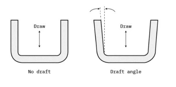
DRAFT ANALYSIS USING CATIA
1. Selection of dummy Tool Axis -
Firstly, observe the given part in all planes and select the best which suits the proper mould opening.
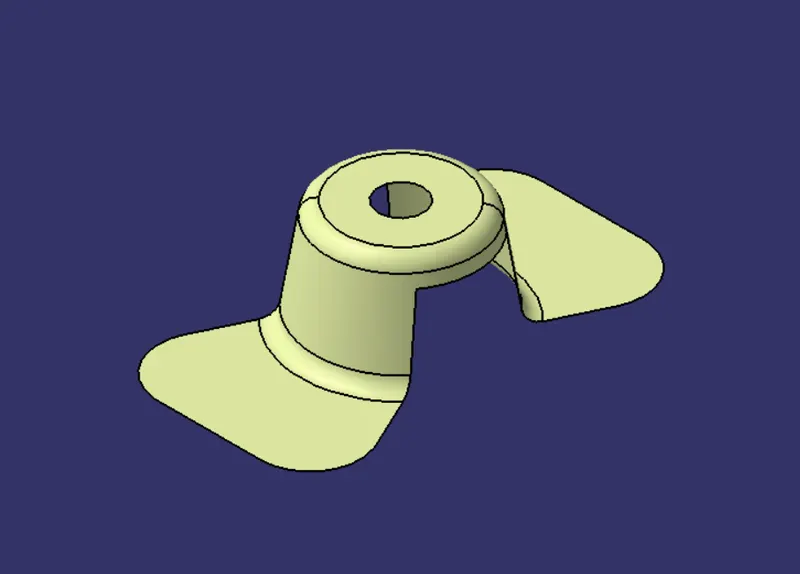
From the given Fan Cover surface, we observed that, the mold opening is possible in z direction because the there is a hole which lies off the XY plane.
So take Z direction as the tool axis, which was the direction the mold will open.
2. Checking open gaps -
Make sure that all the surfaces are closed and joined properly and has no discontinuity. Use Boundary or Join command to check the open gaps.
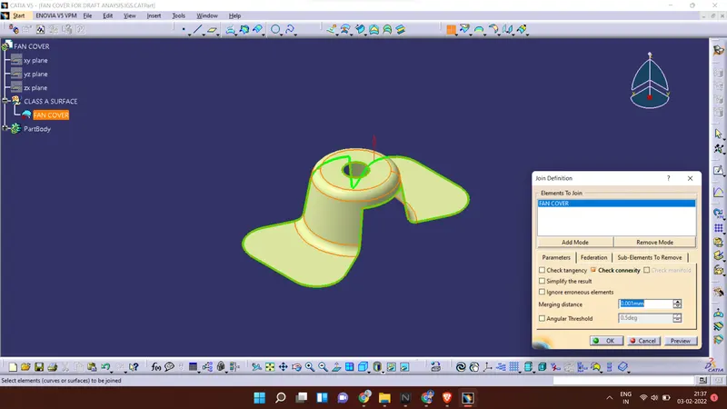
3. Creating Boundary
Create a boundary curve on the open edges of the fan cover using boundary option
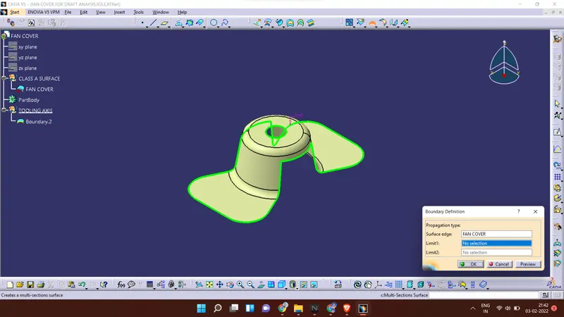
4. Create dummy tooling axis -
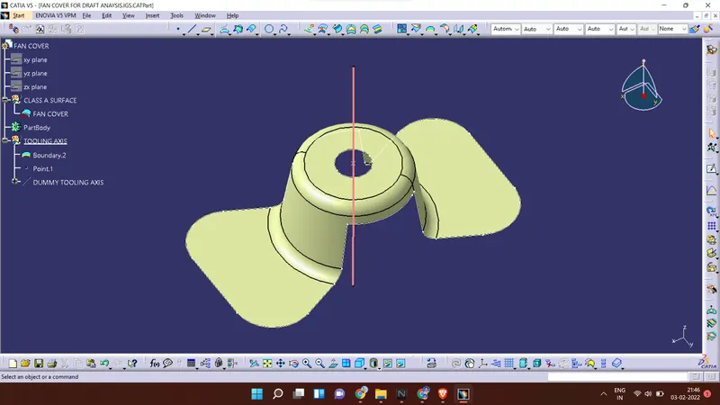
5. Insert a new axis system with reference to the dummy tool axis
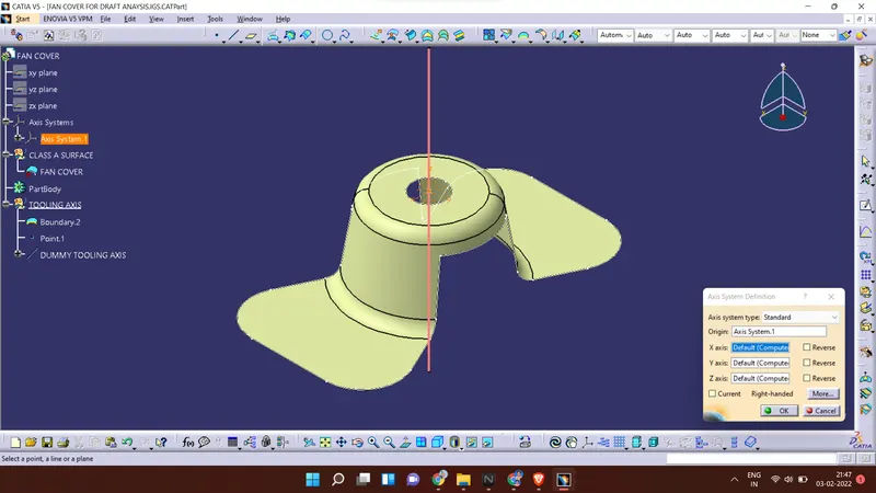
6. Create an intersection line of XZ plane on surface
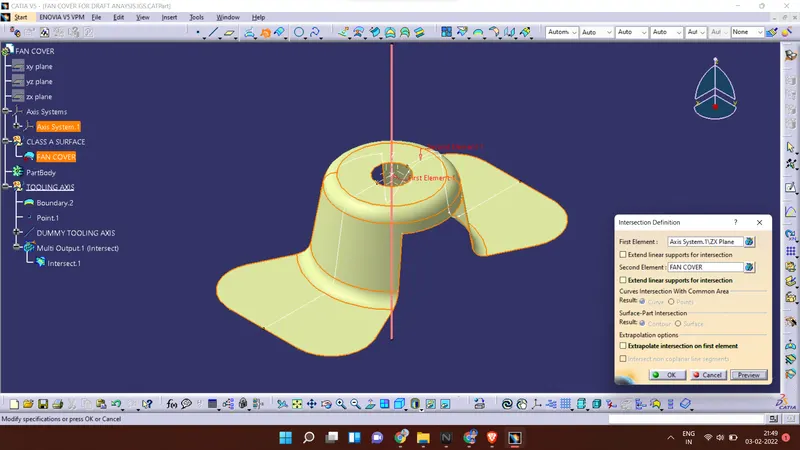
7. Find out the tooling axis in X direction
Create a line extending the drafted faces
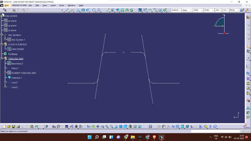
8. Bisect the both the lines
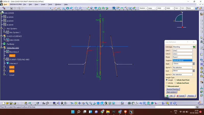
9. Find out the tooling axis in Y direction
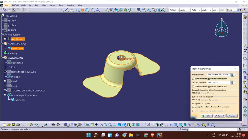
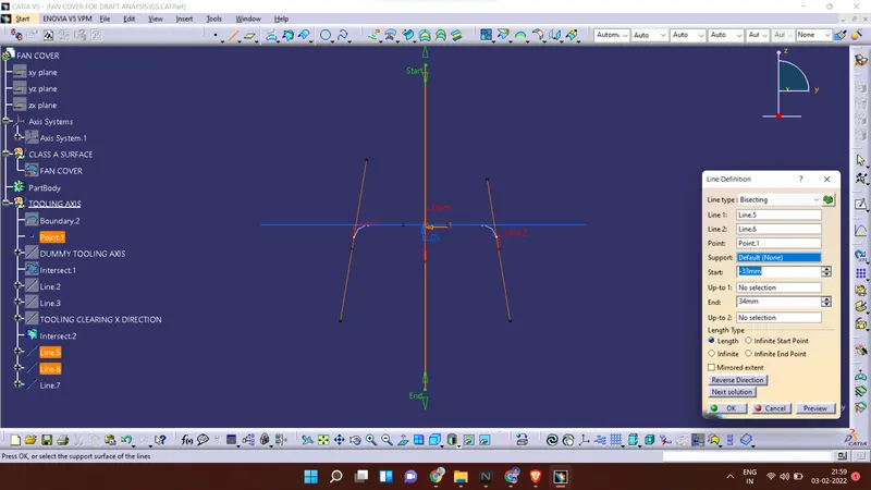
10. Bisect both X and Y tooling axis
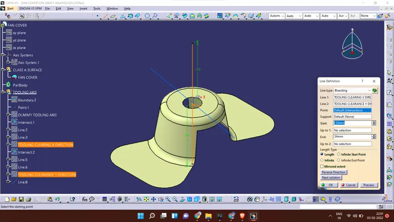
This line is the tooling axis
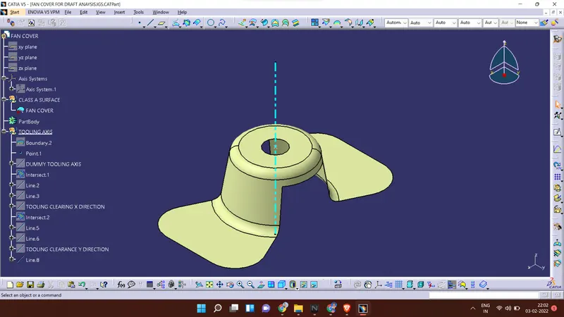
Publish Tooling axis and Class A surface
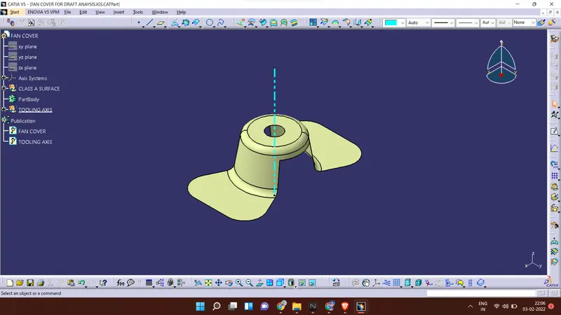
DRAFT ANALYSIS :
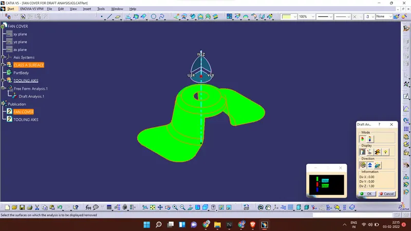
Open the draft analysis window and change the angle to 3 degrees
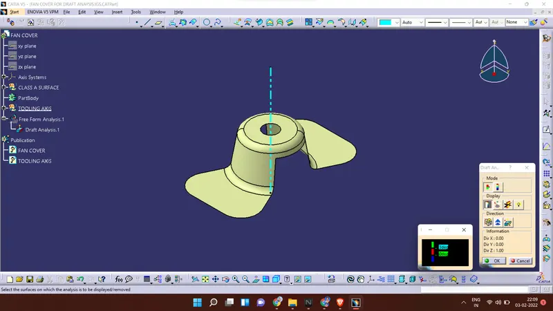
Take the compass and position it and lock the position of the compass
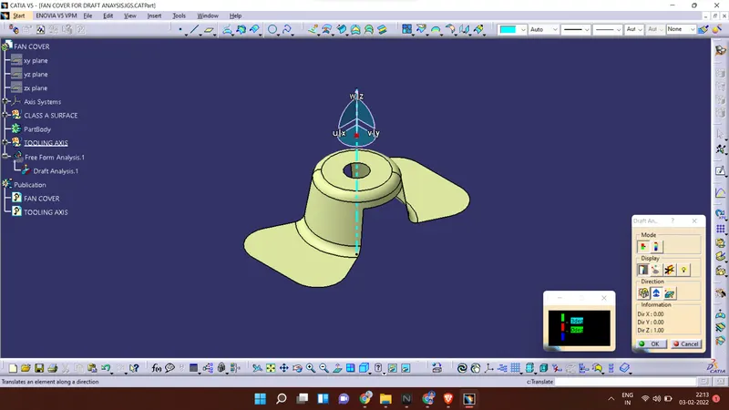
Checking the minimum draft
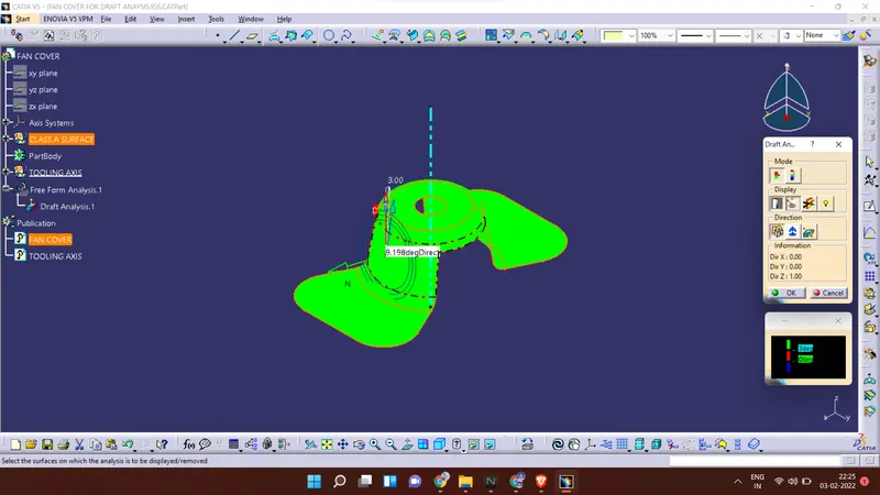
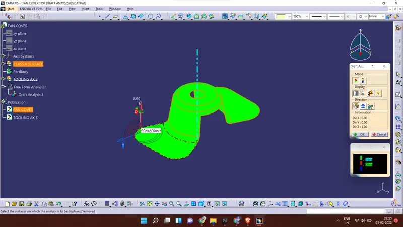
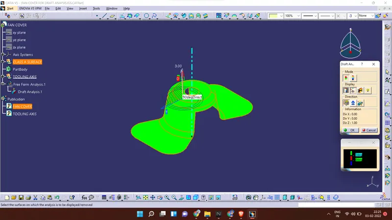
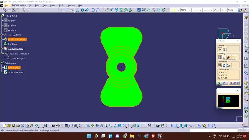
From the below picture, the surfaces with green color represents the minimum draft of 3 degrees, and it is good for manufacturing. If any face showing red, it has no draft and surface in blue color indicates the negative draft.
In the below picture, red and blue surfaces are not found then it has a good drafting surface.
Full analysis mode
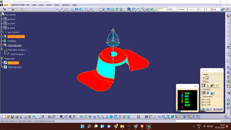
Views :
Isometric view
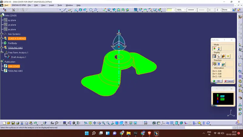
Front view
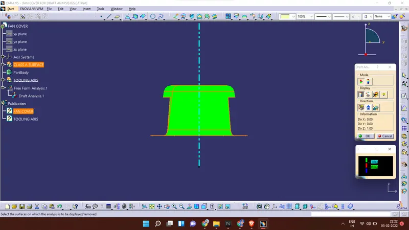
Side view
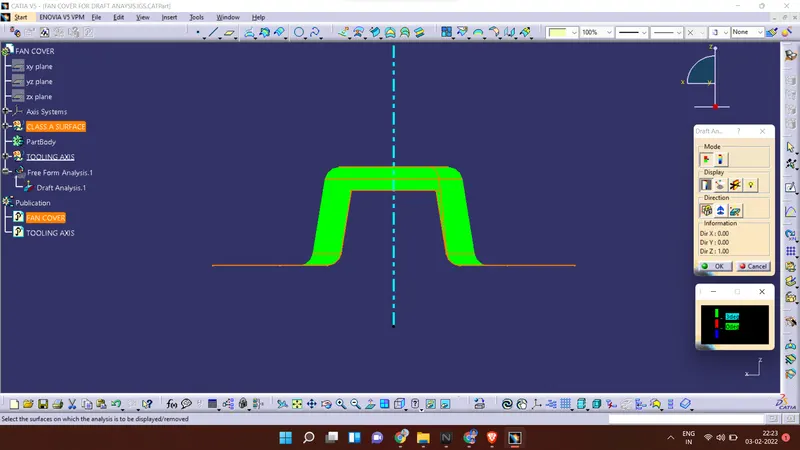
Top view
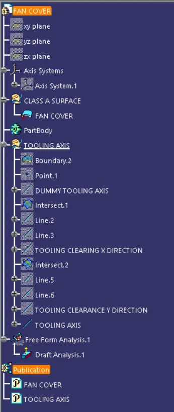
Tree structure :
Conclusion :
The draft analysis is done on the given class A surface of the fan cover, and it is found that the surfaces are having the minimum draft, and it is suitable for manufacturing.
Thank You