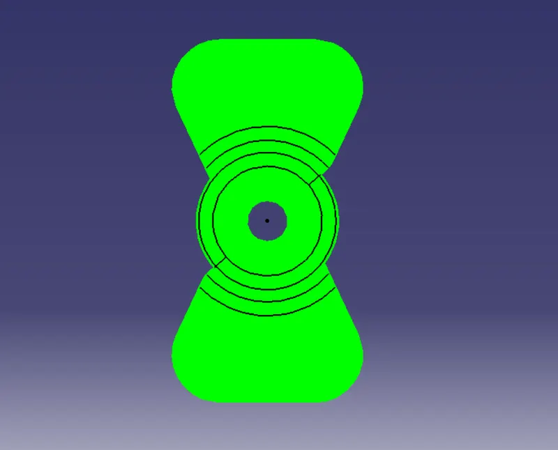
Week 8 - Challenge 1 - Draft Analysis on a Fan Cover
AIM:
To create a tooling axis for a fan cover model which satisfy all the rules of draft angle and perform the draft analysis on the model.
OBJECTIVE:
- Ensure proper tree structure.
- Ensure proper names for every geometrical set according to sketches.
- All sketches should be under the Geometrical set.
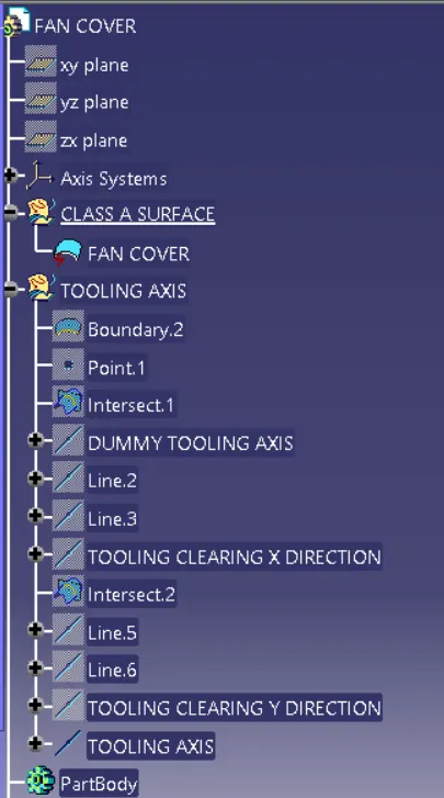
- Publication of tooling axis and class-A surface.
OPERATIONS INVOLVED:
DRAFT: Draft is amount of taper for molded or cast parts perpendicular to the parting line.
PULLING DIRECTION:The direction from which part is ejected from the mold is called pulling direction. This direction also corresponds to the reference from which the draft faces are defined.
DRAFT ANGLE: A draft angle is angle which is applied to each side of most features of injection moulding part. The angle which is posyioned to run towars the direction of mold's pull an parting line.
NEUTRAL ELEMENT: It is the neutral curve on which the drafted angle will lie. Neutral and parting lines may be same in some cases.
DRAFT ANALYSIS: This command enables you to detect if the oart you drafted will be easily removed . This type of analysis is performed based on colour ranges identifying zones where the deviation frrom the draft direction at any point corresponds to specified values.
TOOLING AXIS: The definiton tab on the tool as dialog this controls how you want tool to orient itself at the same time cutting a multi-axis toolpath. The direction in which mold or core and cavity opens is tooling axis.
TOOLING AXIS
Step-1:
To import the given class-A surface model in this case fan cover model in CATIA V5.
Step-2 :
Test the boundries in the model.
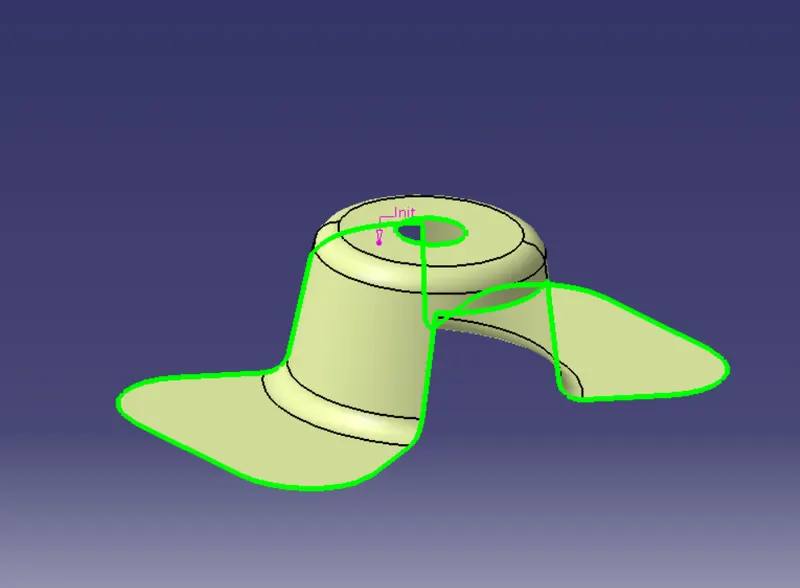
Step-3:
To create tooling axis , first create a dummy axis in the Z-direction by creating a centre point using hole as reference in the point tool.
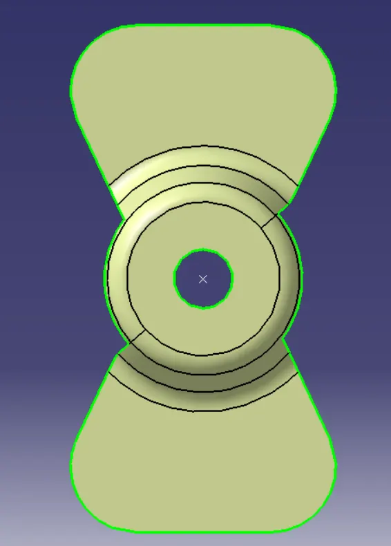
In order to create a tooling axis clearing the direction first which needs to create a axis system at the center point(reference point).
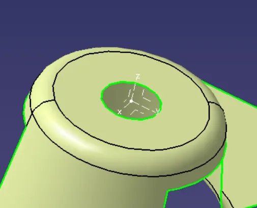
Step-4:
Now using the intersect option on the toolbar, select the ZX plane of the axis system as the first element and fan cover or class-A surface as the second element. This will give a 2D sketch of fan cover viewing from X-direction.
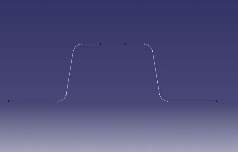
Step-5:
Create a Dummy axis as shown in below image.
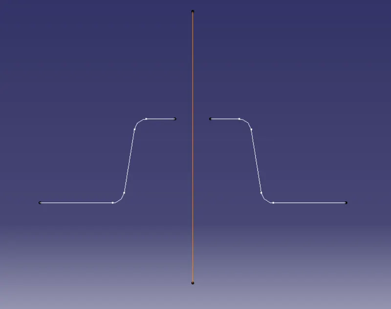
Step-6:
Now create lines representing the walls of the fan cover using point to point in the line command as shown below figure.
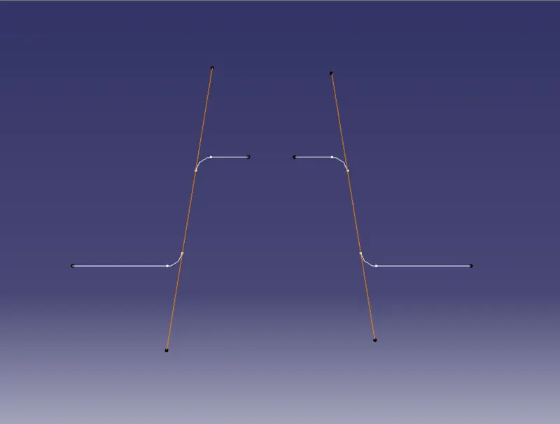
Step-7:
Using the 2lines , create a tooling axis clearing the X-direction. Create a line that bisects these two lines from reference point in Z-direction. This will create a tooling axis clearing X-direction.
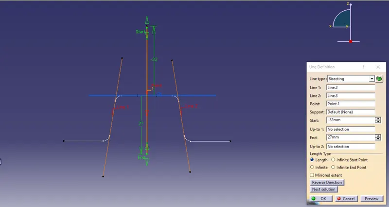
Again using intersect option select YZ plane in the axis system which will give outer lines of the model in Y-direction as shown below.
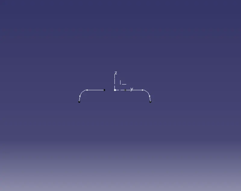
Step-8
Same as before create two lines from the points on the side lines of sketch using point to point in line command as shown below.
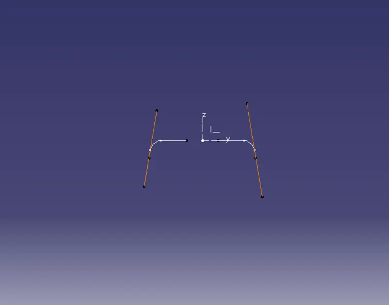
Step-9:
Similarly create a tooling axis clearing Y-direction using same bisecting method as before as shown below
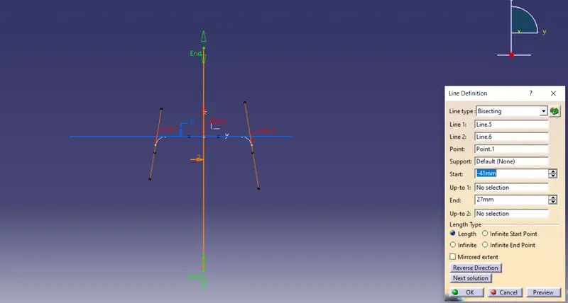
Step-10:
Now create the final tooling axis in the Z-direction for class-A surface using bisecting taking both X and Y direction clearing axis as reference in the line command as shown below.
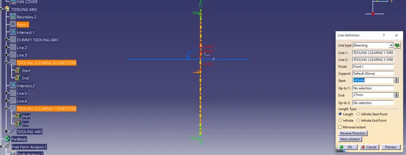
DRAFT ANALYSIS
Step-11:
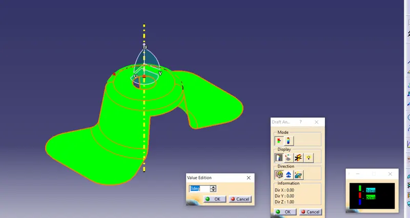
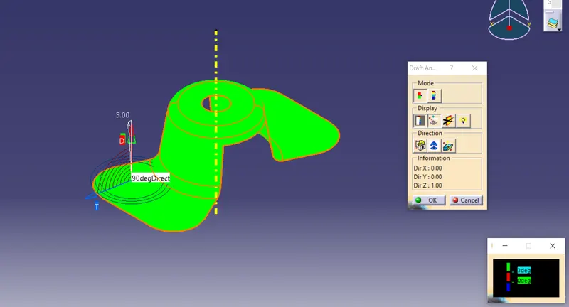
To perform draft analysis on the model: Go to menu bar > Analysis > Feature Draft analysis. to give draft direction use the compass and align Z-axis of it with tooling axis. Once it properly aligned , lock the draft direction. A red point shown on the screen ,select class A-surface and it will show us the current of the model . then go to display tab on draft analysis and select the first option under it colour scale and it will show draft value .set the value to 3 deg under the colour scale variat and press ok.here analysis can be done in two ways quick analysis and full anaysis we choose quick analysis
RESULT:
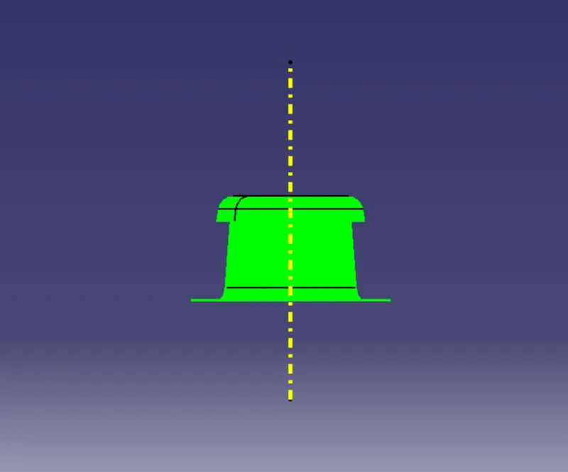
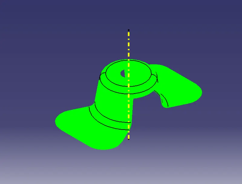
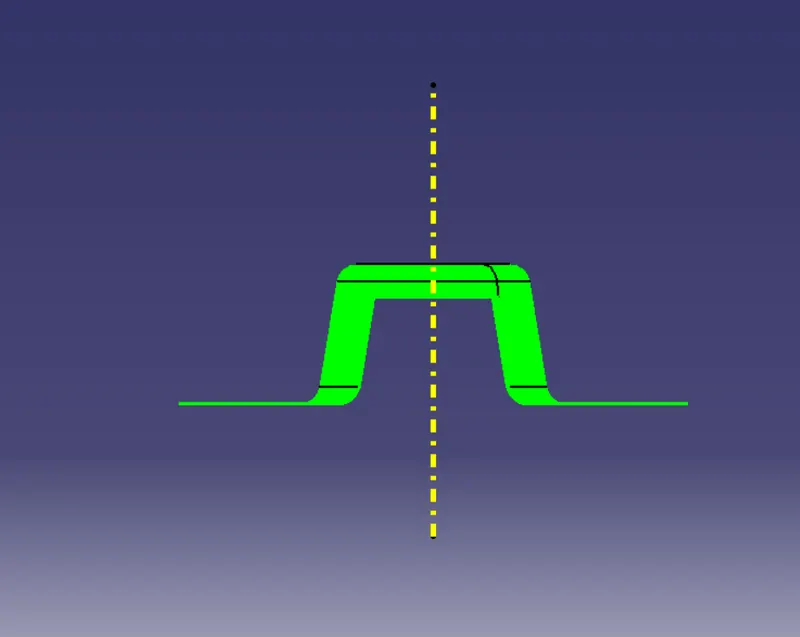
Here draft analysis shows
- The Green colour is drafted walls above 3 degree.
- The Red colour is drafted walls above 0 degree.
The analysis shows the drafted walls of fan cover model are above the par of 3deg which is permissible to manfacture in injection modeling.
The Running point analysis hovered along the drafted walls show parts are above 3 and will easily cleared from ejection.