Week 8 - Challenge 4 - Coin Holder Design
AIM:
To create Centre Console Coin Holder and add thickness to it and generate that draft analysis on a solid surface.
OBJECTIVE:
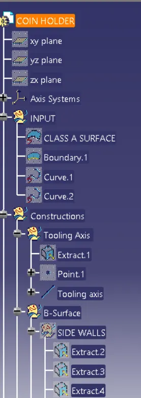
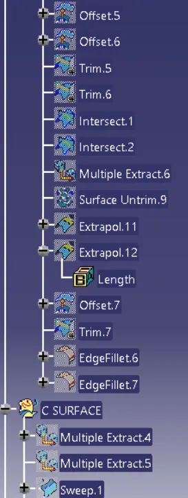
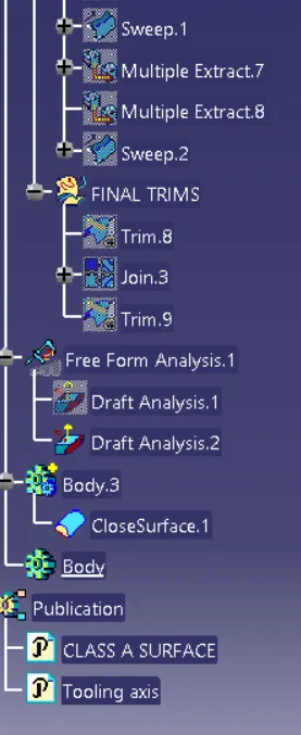
- Ensure proper tree structure.
- Ensure proper names for every geometrical set according to sketches.
- All sketches should be under the Geometrical set.
- Creating a solid surface using closed surface feature from the given surface.
- Publication of tooling axis,class-A surface,class-B surface,class-C surface.
- Performing Draft analysis on class-A surface and final closed solid body.
Design Methodology:
Procedure for tooling axis creation
Tooling direction is created by considering the ejection from cavity of mould after manfacturing the interior trim must have nominal 3 deg draft angle and bisecting method is used.
the base surface of class-A was extracted and point at centre is created and an axis system was inserted to the point by deselecting the current feature option
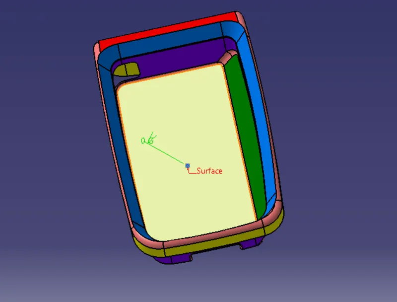
A line is created with point direction option and line is created in z direction this acts as tooling axis. As we can obsereve all surfaces can be drafted this is taken an tooling axis. (note: similar tooling axis can be created using bisecting method which is not necessary as there are no complex surfaces to be drafted)
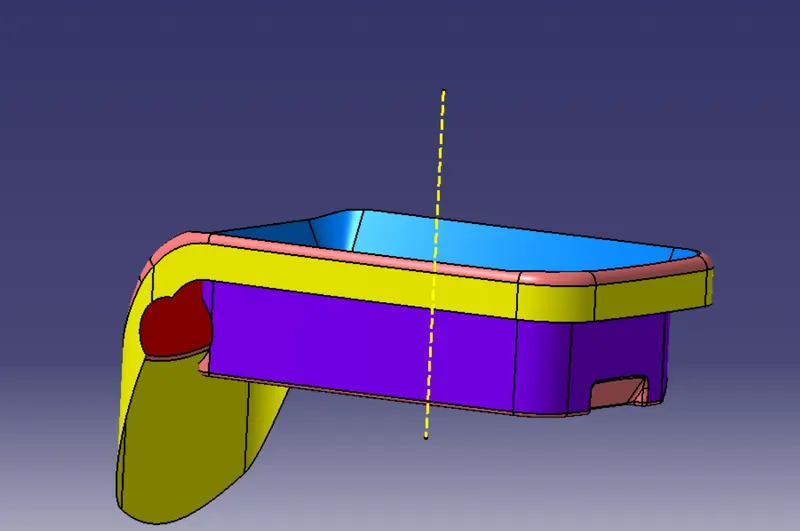
CREATING B SURFACE:
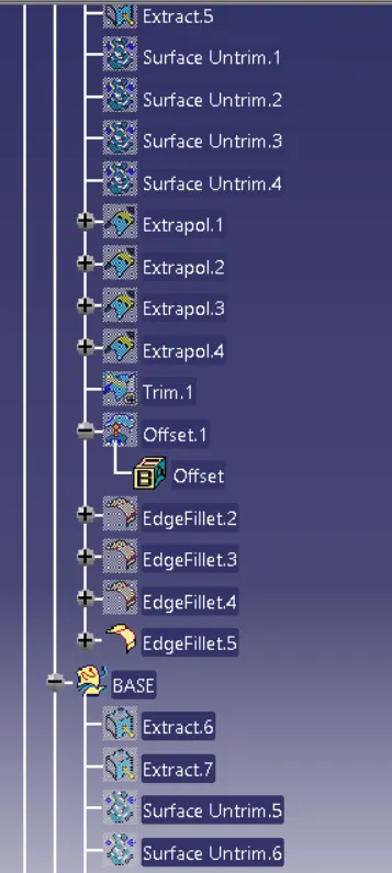
Now create a geometrical set in a tree and name it . extract the side wall surface of center console coin holder by extract option by selecting faces. select the faces
Untrim the extracted surface using the untrim option by selecting surfaces
Extrapolate the untrimmed surfaces using the extrapolate option.Extrapolate definition : boundaries-select the edge of the untrim surface and extrapolate - untrimmed surface and offset the surfaces to 2.5mm in the opposite direction to class-A surface.
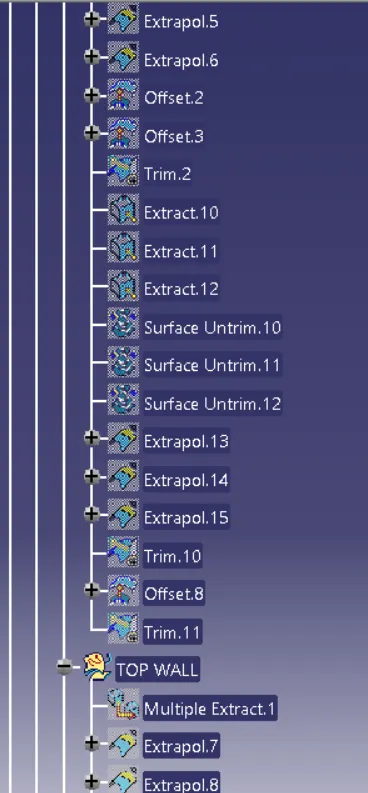
Extract the base surface and block and do the same process and offset the surface to distance of 2.5mm in downward direction
Trim the excess portion of surfaces using trim option
Do the same process for inclined walls surface and outside wall surface by extracting and offsetting the surface and trim the component
Add the fillets at wall's edges
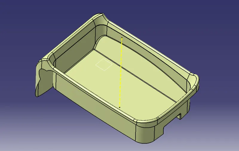
CREATING C SURFACE:
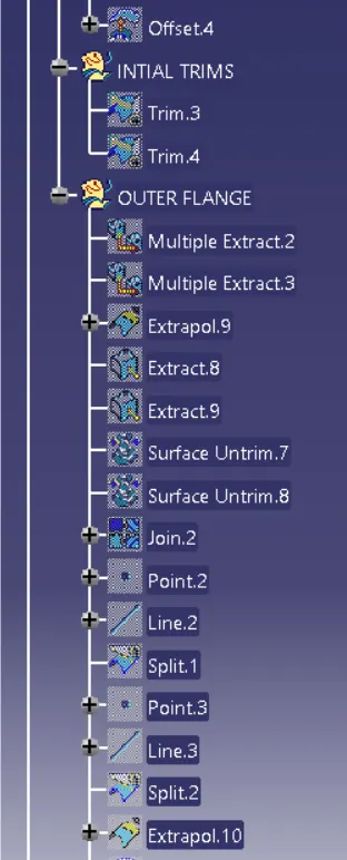
Create the class C surface for class A surface by using the multi extract option by selecting the boundaries . create a smooth curve for the extracted boundary
Extract the outer boundary walls and replace the multi-extract boundary with smooth curve
Now using the sweep option create the c-surface by selecting the with reference surface and guide curve as boundary which is extracted and reference surface as extracted boundary surface and angle of 90-93deg to maintain draft angle
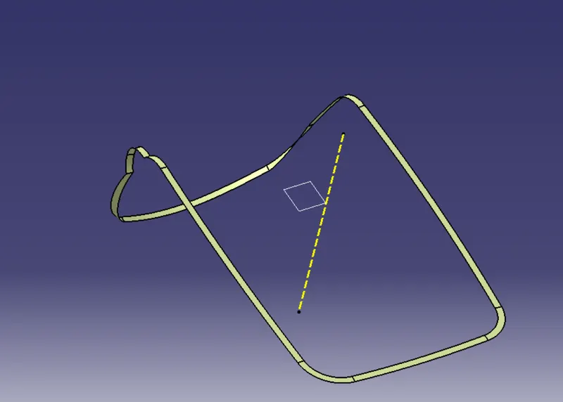
Join the surfaces and trim the surfaces with class B and class C
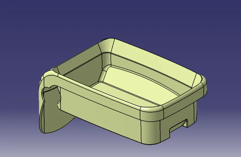
Check for any open boundaries in a plastic design snd create the solid surface for the design in part design using a closed surface option
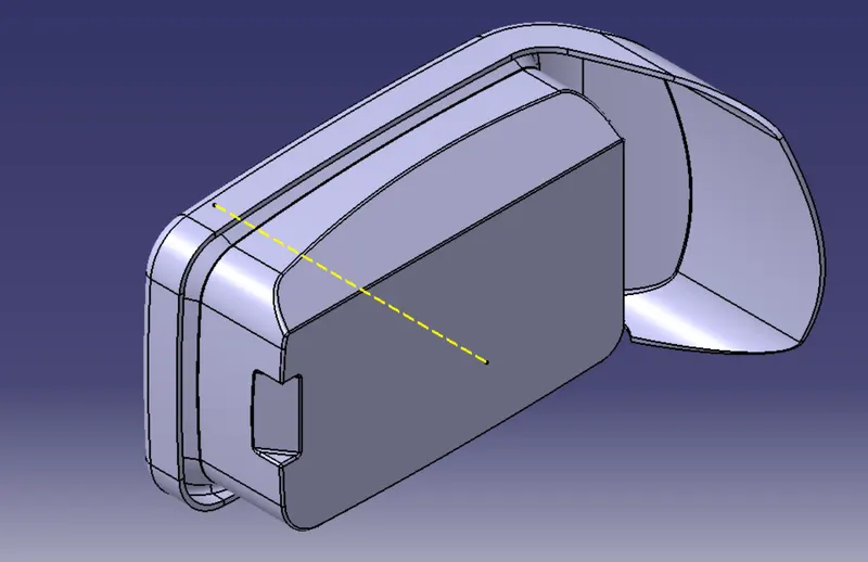
DRAFT ANALYSIS(Class-A Surface):
To perform draft analysis on the model: Go to menu bar > Analysis > Feature Draft analysis. to give draft direction use the compass and align Z-axis of it with tooling axis. Once it properly aligned , lock the draft direction. A red point shown on the screen ,select class A-surface and it will show us the current of the model . then go to display tab on draft analysis and select the first option under it colour scale and it will show draft value .set the value to 3 deg under the colour scale variat and press ok.here analysis can be done in two ways quick analysis and full anaysis we choose quick analysis.
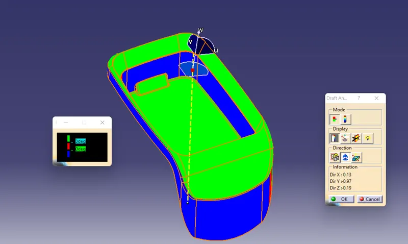
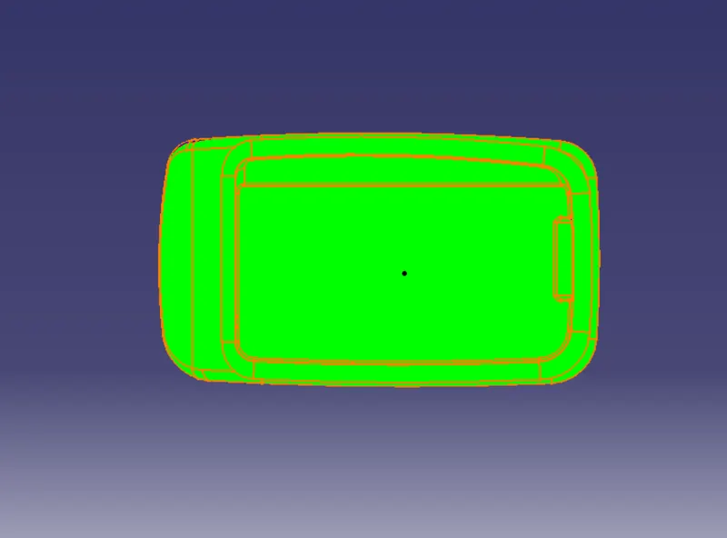
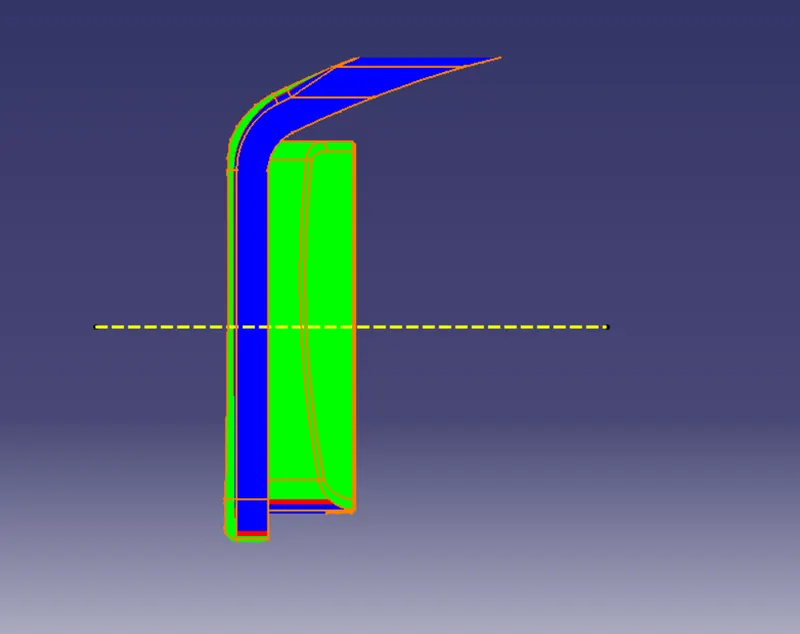
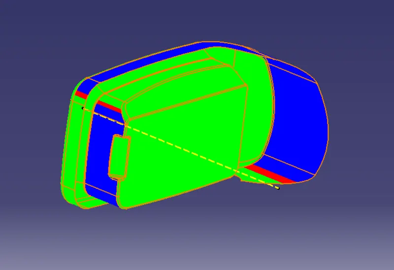
Here draft analysis shows
- The Green colour is drafted walls above 3 degree.
- The Red colour is drafted walls above 0 degree.
The analysis shows the drafted walls of Coin holder are above the par of 3deg which is permissible to manfacture in injection modeling. except some surfaces which are to modified
DRAFT ANALYSIS(Solid body):
To perform draft analysis on the model: Go to menu bar > Analysis > Feature Draft analysis. to give draft direction use the compass and align Z-axis of it with tooling axis. Once it properly aligned , lock the draft direction. A red point shown on the screen ,select class A-surface and it will show us the current of the model . then go to display tab on draft analysis and select the first option under it colour scale and it will show draft value .set the value to 3 deg under the colour scale variat and press ok.here analysis can be done in two ways quick analysis and full anaysis we choose quick analysis.
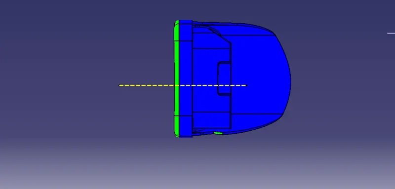
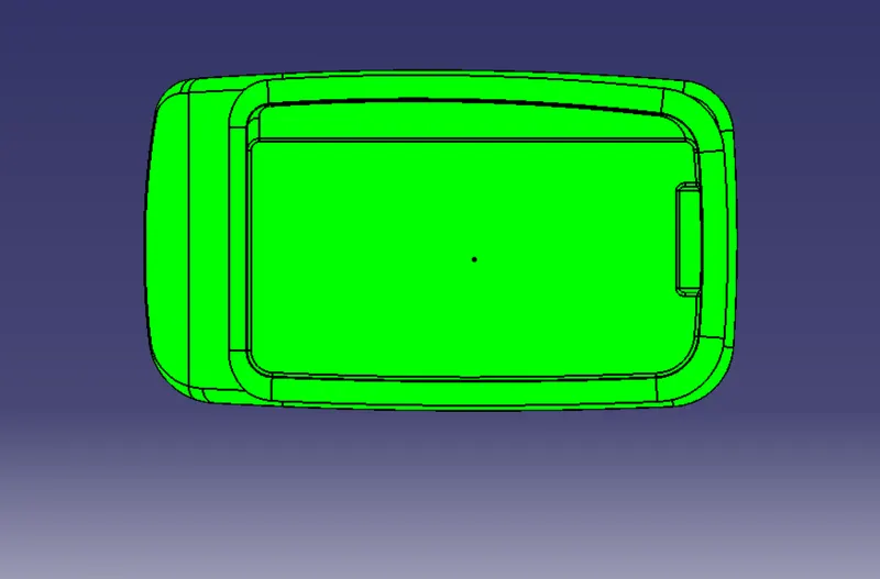
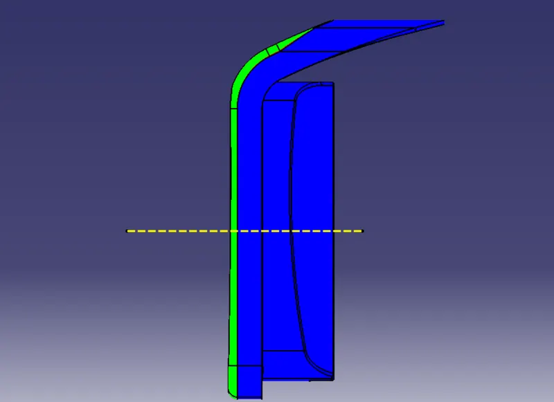
Here draft analysis shows
- The Green colour is drafted walls above 3 degree.
- The Red colour is drafted walls above 0 degree.
The analysis shows the drafted walls of Base bracket are above the par of 3deg which is permissible to manfacture in injection modeling. same as above except some surfaces which are to be modified in class A surface.