Week 8 - Challenge 3 - Switch Bezel Design
AIM:
To Create solid part body of SWITCH BEZEL from given Class-A surface.
OBJECTIVE:
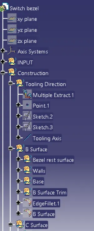
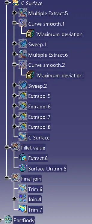
- Ensure proper tree structure.
- Ensure proper names for every geometrical set according to sketches.
- All sketches should be under the Geometrical set.
- Creating a solid surface using closed surface feature from the given surface.
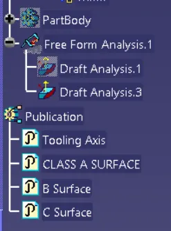
- Publication of tooling axis,class-A surface,class-B surface,class-C surface.
- Performing Draft analysis on class-A surface and final closed solid body.
Design Methodology:
Procedure for tooling axis creation
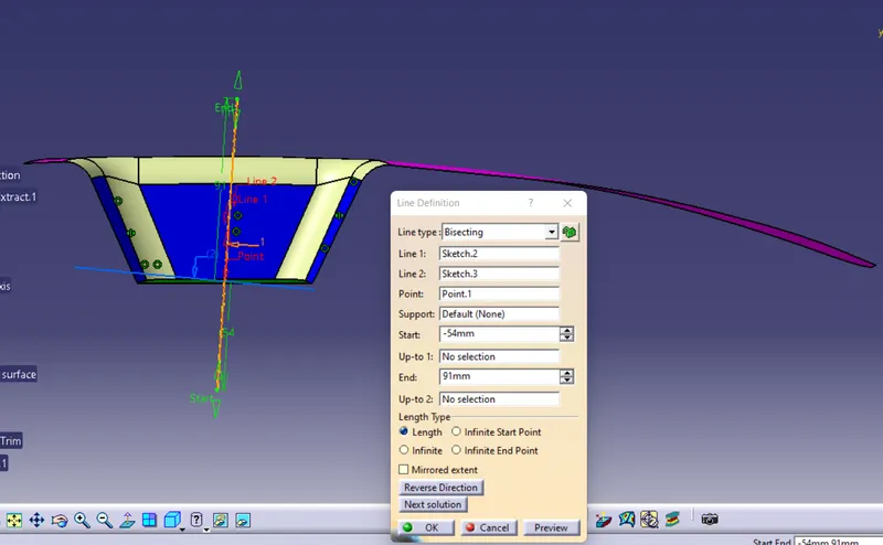
Tooling direction is created by considering the ejection from cavity of mould after manfacturing the interior trim must have nominal 3 deg draft angle and bisecting method is used.
the base surface of class-A was extracted and point at centre is created and an axis system was inserted to the point by deselecting the current feature option
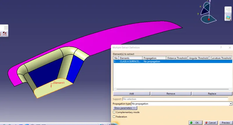
Then using project intersection along YZ plane is created and two inclined lines were drawn inside positioned sketch.then bisecting line with two inclined lines were drawn.
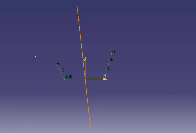
Now the same is done along the XZ plane but on side there is no inclined line .so the centre point is used to extrude a line along the Z-direction 5.5 deg angle given.
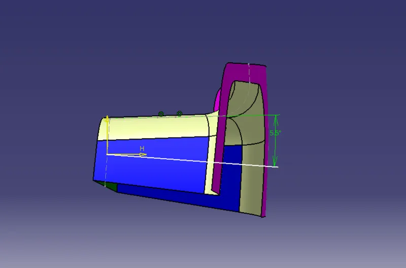
With these two lines from Sketch 1 and Sketch 2 the Bisecting line is created and published as tooling axis.
CLASS-B SURFACE CREATION
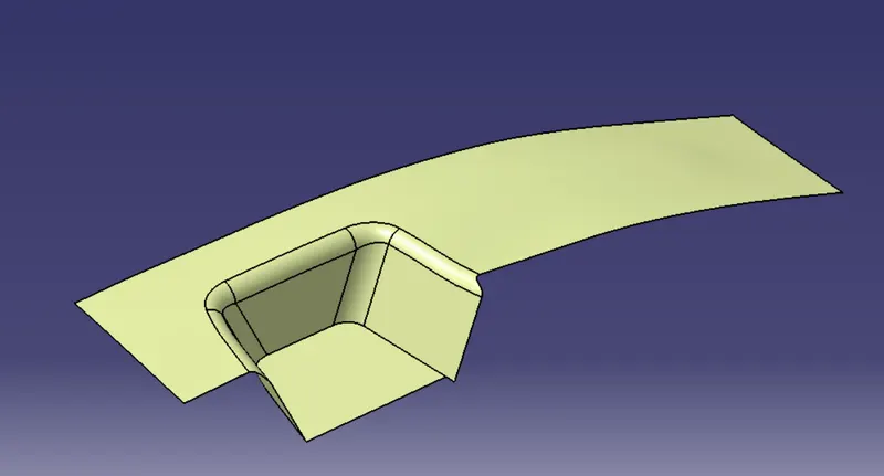
For creating the class-B surface the required surface except the offset surface have been extractedand then untrimm all the surfaces.
Then all the surfaces have been extrapolated to get intersections between them.
Since thickness of switch bezel is 2.5mm the B-surface was offset to 2.5mm and the required trim operations must be carried out.
Finally , the required corners have been filleted to aprrox 13mm(Fillet value of A surface - thickness of component).
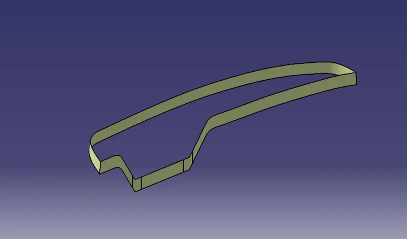
CLASS-C SURFACE CREATION:
The required outer edges of A-Surface were extracted using multiple extract . then for avoiding the patches the curve is smoothened using curve smooth option.
Then by using the sweep command the surface was created.then by using extrapolate command the edges were intersected between surface corners which eases the trimming operation.
Now required C-Surface is formed by trimming both edges.
CLOSED SOLID SURFACE:
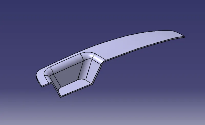
Now join the class-A and C-surface and check for any open surfaces if present trim class A,C surfaces. then join trim surface to make it one surface now trim these with B-Surface.
Then ,by defining the part body using closed surface command in part design thus solid body is created.
DRAFT ANALYSIS(Class-A Surface):
To perform draft analysis on the model: Go to menu bar > Analysis > Feature Draft analysis. to give draft direction use the compass and align Z-axis of it with tooling axis. Once it properly aligned , lock the draft direction. A red point shown on the screen ,select class A-surface and it will show us the current of the model . then go to display tab on draft analysis and select the first option under it colour scale and it will show draft value .set the value to 3 deg under the colour scale variat and press ok.here analysis can be done in two ways quick analysis and full anaysis we choose quick analysis.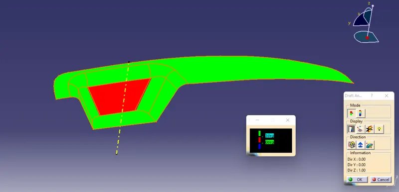
Here draft analysis shows
- The Green colour is drafted walls above 3 degree.
- The Red colour is drafted walls above 0 degree.
The analysis shows the drafted walls of Class-A surface are above the par of 3deg except one surface which should be modified by surface engineer and after modification class-B and class-C surfaces are fromed.
DRAFT ANALYSIS(Solid body):
To perform draft analysis on the model: Go to menu bar > Analysis > Feature Draft analysis. to give draft direction use the compass and align Z-axis of it with tooling axis. Once it properly aligned , lock the draft direction. A red point shown on the screen ,select class A-surface and it will show us the current of the model . then go to display tab on draft analysis and select the first option under it colour scale and it will show draft value .set the value to 3 deg under the colour scale variat and press ok.here analysis can be done in two ways quick analysis and full anaysis we choose quick analysis.
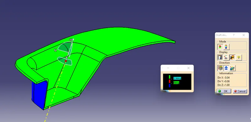
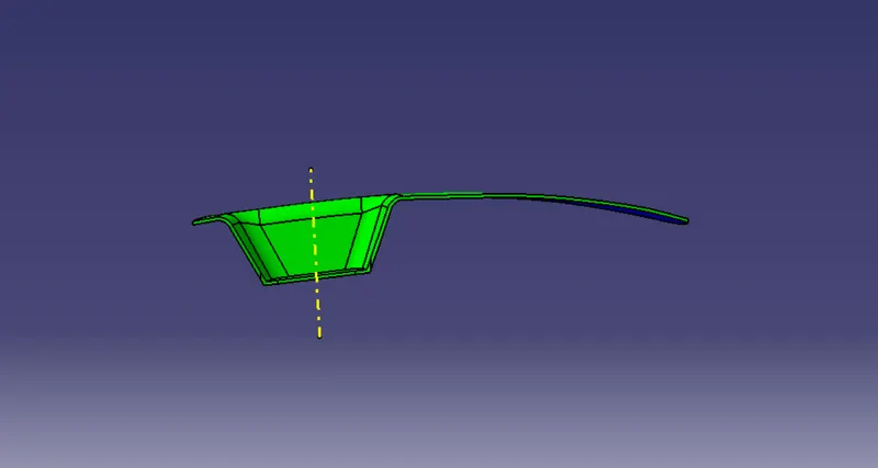
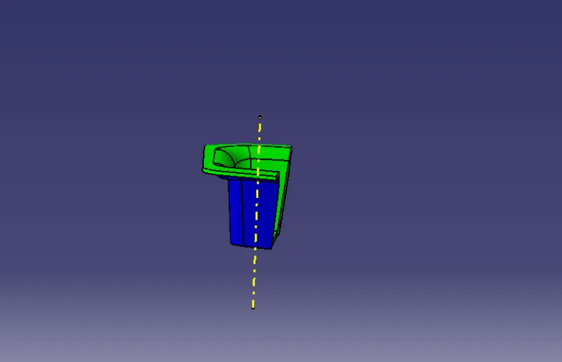
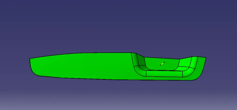
Here draft analysis shows
- The Green colour is drafted walls above 3 degree.
- The Red colour is drafted walls above 0 degree.
The analysis shows the drafted walls of Base bracket are above the par of 3deg which is permissible to manfacture in injection modeling.
The Running point analysis hovered along the drafted walls show parts are above 3 and will easily cleared from ejection.