Week 8 - Challenge 1 - Draft Analysis on a Fan Cover
What is Draft Analysis?
No part can be ejected from the tool if its having straight 90-degree profile from its base surface. A small draft angle is provided to each and every area of the component in order to get an easy removal of the component from the tool. Draft analysis technique used to analysis whether our part model created in CAD is manufacturable based on the draft condition applied. Here the part should get easily removed from the panel dies (in case of sheet metal part) or mold (in case of plastic). Here we are providing a direction in which components should eject in order to get an easy removal of component from tool. In other words, it also les us know whether the model is having draft angle and how much is the draft angle.
Draft analysis is performed on the components where the ejection of the material happens after the material is made inside the tools. In case of automotive sheet metal manufacturing, the blank sheet after turning into automotive panels like hood, fender, Roof, side doors, back doors etc. need to be removed from panel dies. If a considerable amount of draft is not provided, the removal components from the tool will be difficult. Same in case of mold (plastic component) after getting filled inside the core and cavity, it needs to get ejected easily with the help of the ejectors.
Process:
Approach of draft analysis:
First ensure the class A surface is properly joined and has no discontinuity on it. For this we can used join or boundary command.
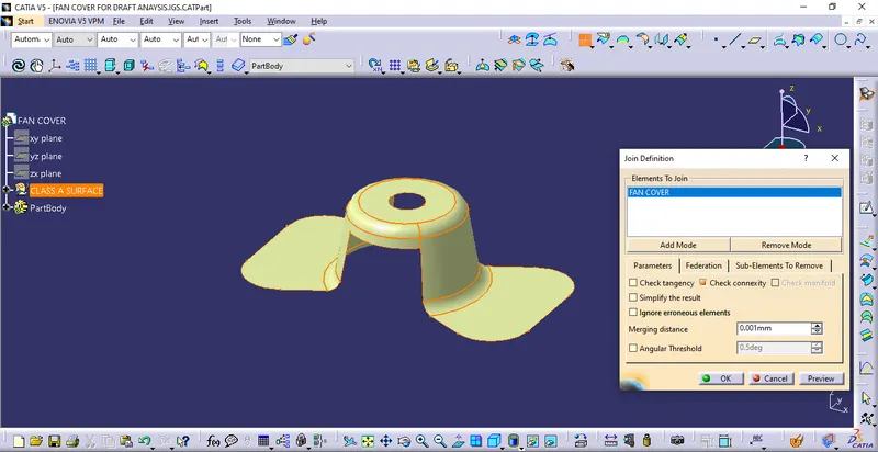
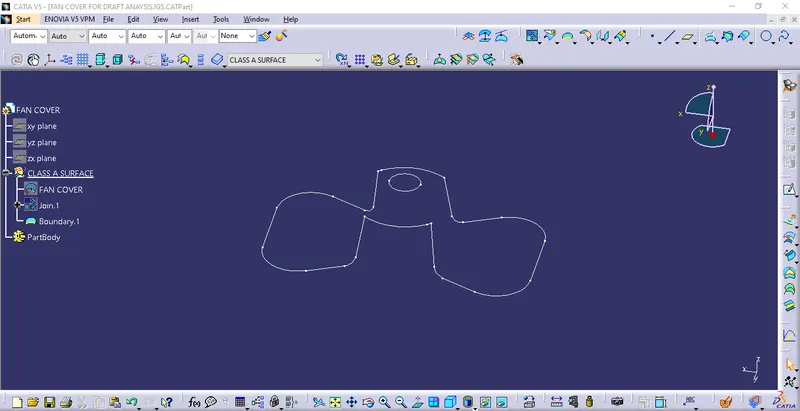
Analyze the model manually or visually to see which direction is most suitable for tooling axis.
Here, we are looking at isometric view of surface we can clearly see the hole on the top face.
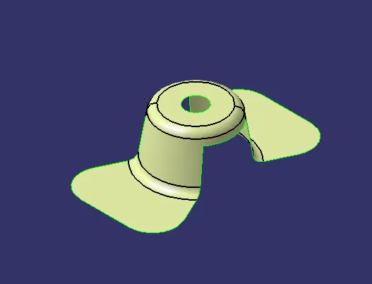
From x direction, it will be difficult for tooling the hole.
Similarly, from Y direction hole cannot be seen thus, it will be difficult to tool it.
But, in Z direction hole can be seen thus we choose this as dummy tooling direction.
Now, we will use the bisecting method to make real tooling axis.
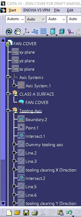
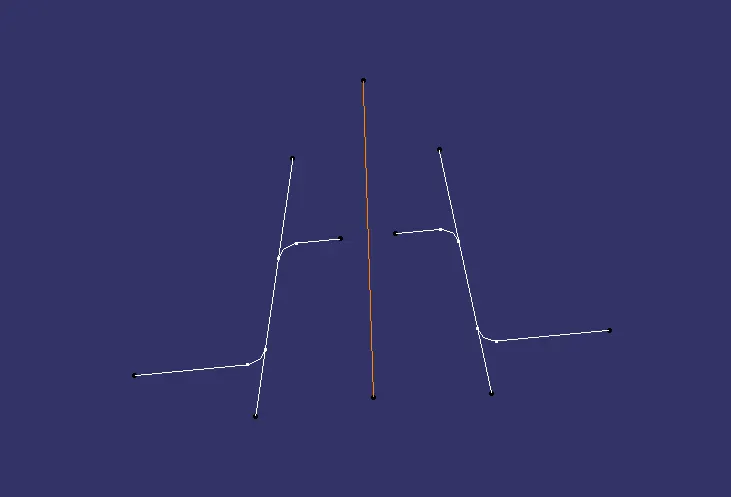
- Make an axis system and intersect ZX plane with class A surface. We will get the line. Now we have to see which surface will create problem or will be difficult to be tooled and make line along that surface using point to point option. Here we can see the picture that we have made two lines, now we will bisect the two lines and choose proper direction, here vertical direction. This will be our tooling axis for x direction.
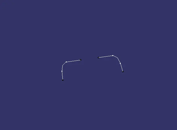
- Similarly, we intersect the YZ plane of the axis system with the class A surface and we repeat the same procedure again.
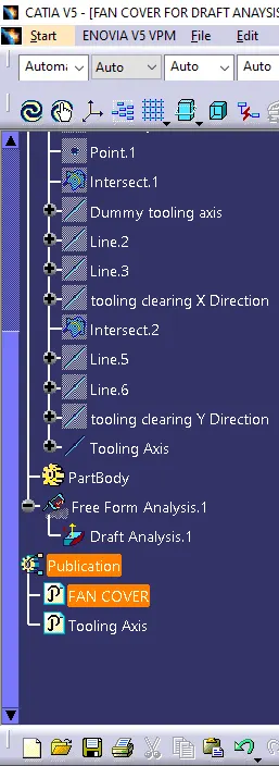
- Now we have two axis tooling clearing in x direction and tooling clearing y direction. We will bisect these two axes to get final tooling Axis.
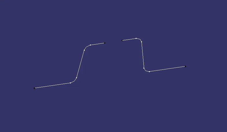
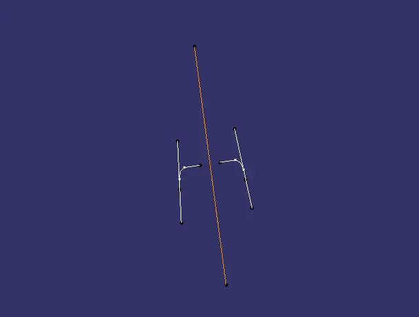
Final Tooling direction:
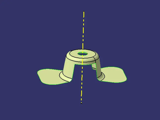
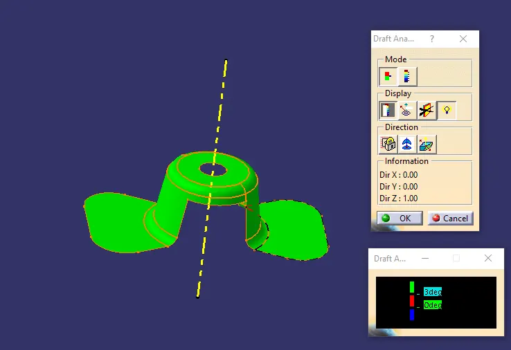
Draft Analysis:
- Go to insert
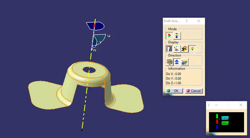
- Click on the compass icon and align it with the tooling axis and click on the surface, we will get our result.