Week 8 - Challenge 1 - Draft Analysis on a Fan Cover
HELLO SIR,
Week 8 - Challenge 1 - Draft Analysis on a Fan Cover
DRAFT ANALYSIS OF FAN COVER
First, I check the connectivity of the (Class A) Fan cover model. Click on the join command & boundary command to check, and to ensure that there is no gap between the surfaces.
After that,
Creation of Tooling Axis
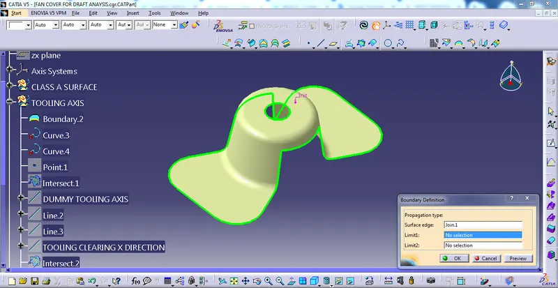
First of all, click the boundary command to create a boundary of the fan cover then, select Boundary 2 and go to disassemble the command to convert into two curves.
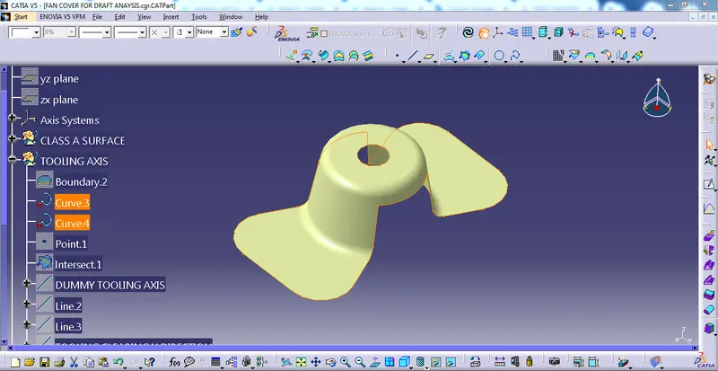
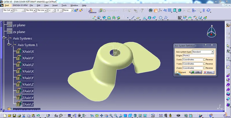
create a point using the point command then create the axis system to the point

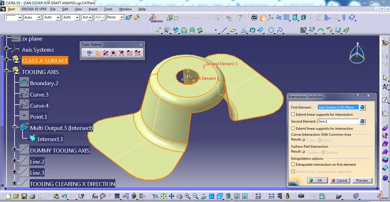
After that, go to the intersection command to intersect the z-x plane
then I created a dummy tooling axis
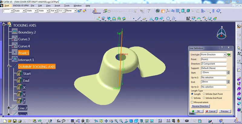
After that, I created two lines using line command then the bisecting two lines
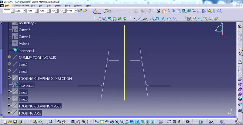
Tooling Clearing X-Direction
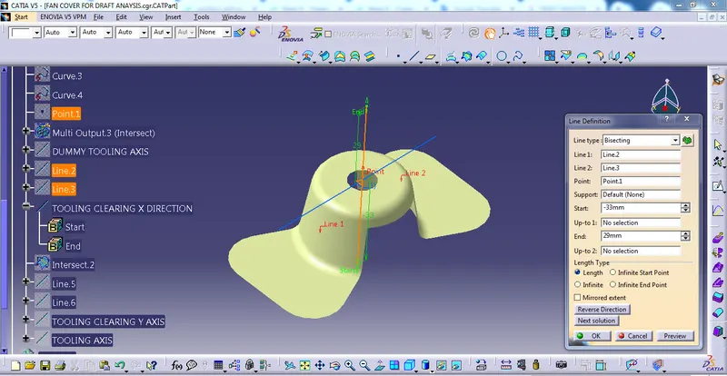
Again I created the intersect in the Y-Z plane and then I follow the same procedure then I created
Tooling Clearing y-Direction
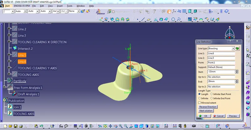
Then bisecting the Tooling Clearing x-Direction and Tooling Clearing y-Direction. finally, we have got main
Tooling Axis
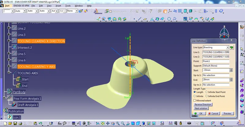
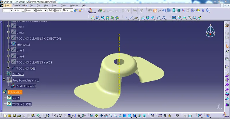
then I Published Tooling Axis and Class A (fan cover).
DRAFT ANALYSIS-
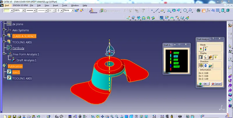
The Draft Analysis command enables you to detect if the part you drafted will be easily removed. This type of analysis is performed based on color ranges identifying zones on the analyzed element where the deviation from the draft direction at any point, corresponds to specified values.
Procedure to the draft analysis of fan cover
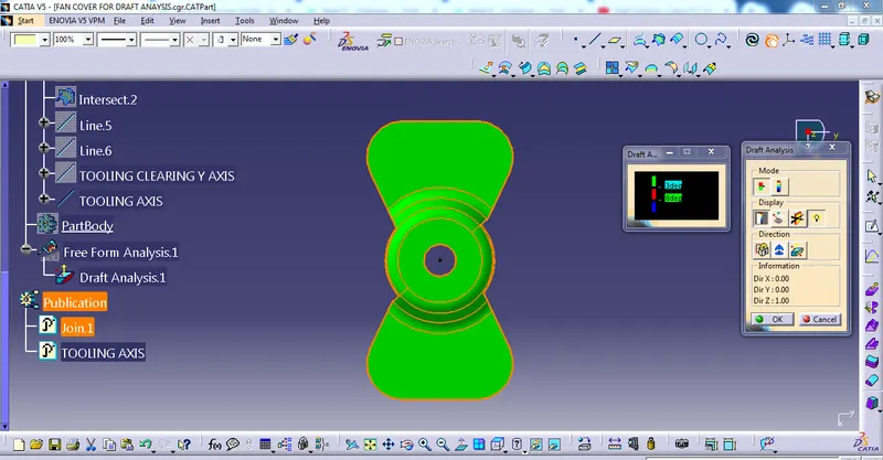
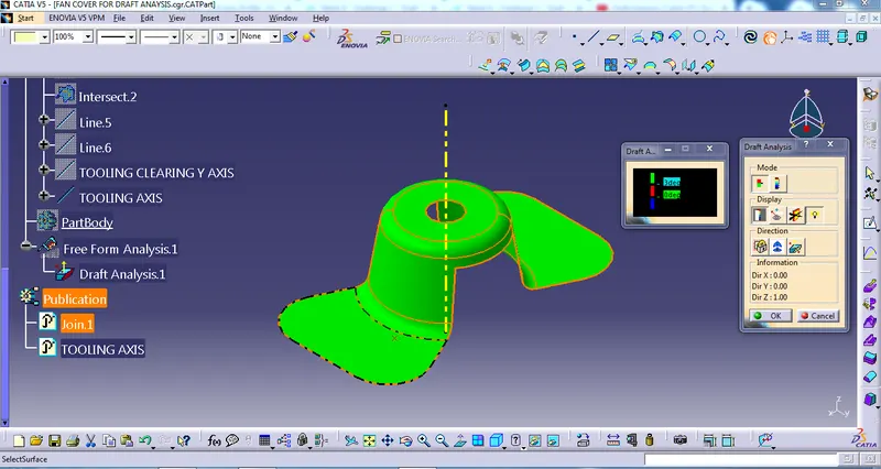
First, we have to customize the view parameter, I select the materials option, and go to the draft analysis command it will appear on the screen
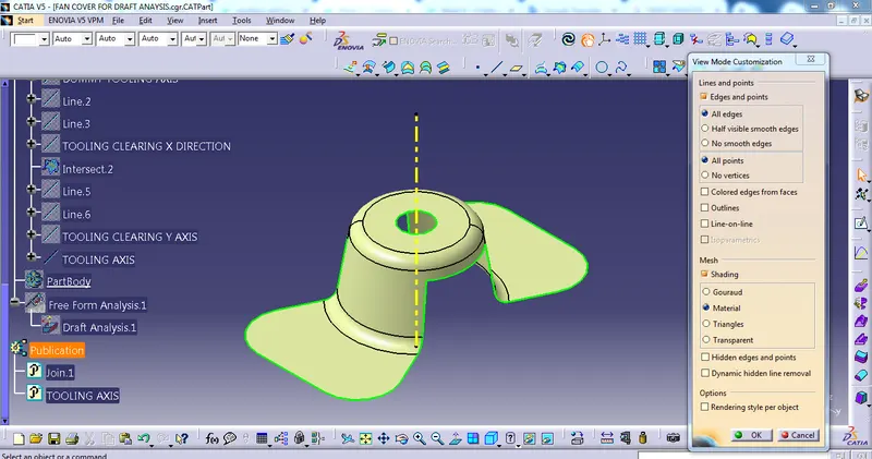
QUICK ANALYSIS MODE
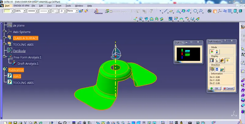
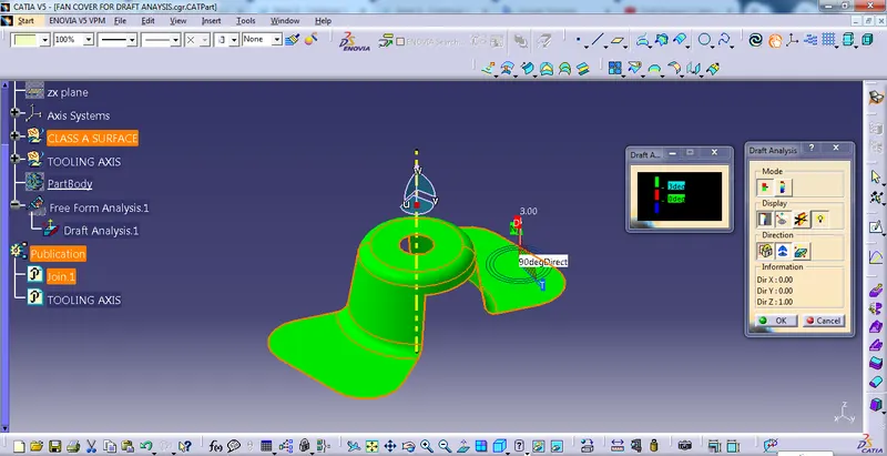
FULL ANALYSIS MODE
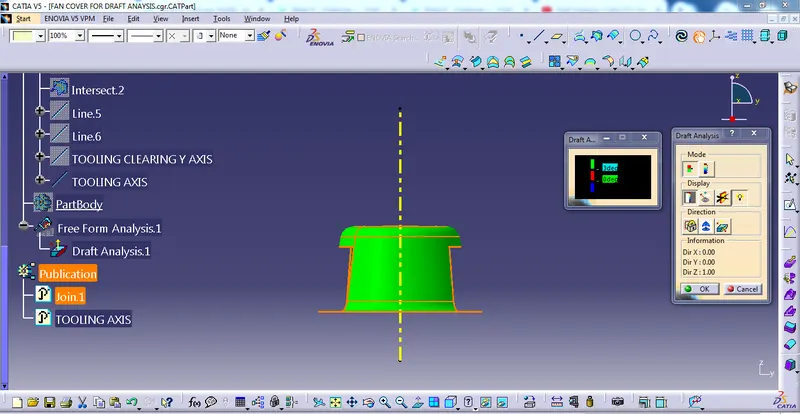
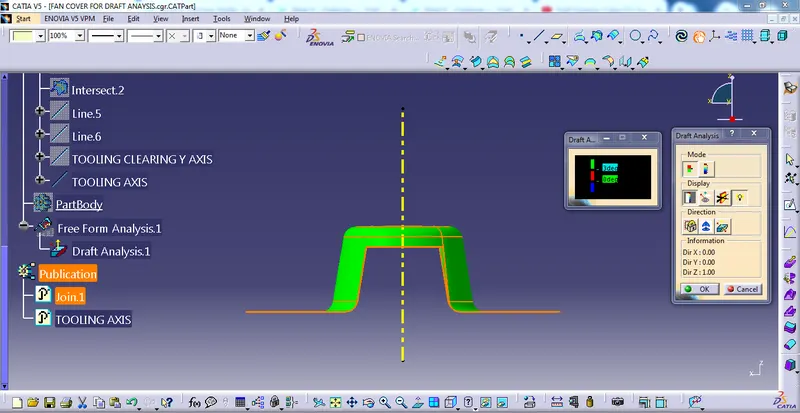
FRONT VIEW, TOP VIEW, SIDE VIEW & ISOMETRIC VIEW OF FAN COVER
THANKS