Week 8 - Challenge 1 - Draft Analysis on a Fan Cover
*Creating tooling axis for the given model & Performing Draft Analysis on it.
Draft Analysis:
Draft Analysis is an analysis technique which lets us know whether the component (plastic or sheet metal) is manufacturable or not. While the plastic component is manufactured in injection molding, component should have a draft angle (ref. to tooling axis) of 0.5 to 3 degrees, while the sheet metal has 7 degrees draft angle. The tooling axis the direction the mold opens and closes to eject the manufactured component.
Draft Angle:
Draft Angle is an angle which is given to the surfaces which are parallel to the tooling axis. This Angle is given inorder to eliminate shrinkages or wear & tear of the material and which causes damage to the tool also. Generally draft angle of a plastic component ranges from a minimum of 0.5 deg to a maximum of 3 deg, 3deg above can also be considered but the cost of tooling makes it much expensive, So it better to be considered at 3 degrees. No parts can be ejected from the tool if the component is having a straight 90 degree profile from its base surface. A negative draft angle should not be given to any material whether it is plastic or sheet metal while manufacturing. So, a small draft angle is provided to each and every area of the component to obtain easy removal of the component from the tool.
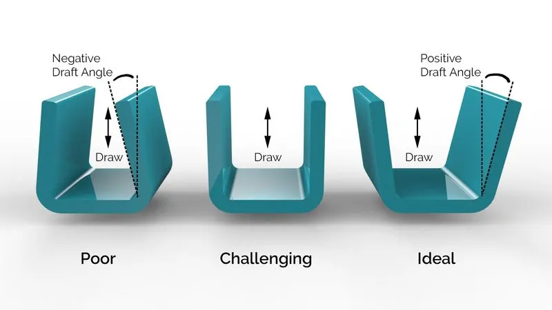
*Performing Draft Analysis.
*This Draft Analysis is performed according to Bisecting method.
*Bisecting method is the method in which the surfaces of the material bisects to an axis, where that axis is considered as the tooling axis.
Component:
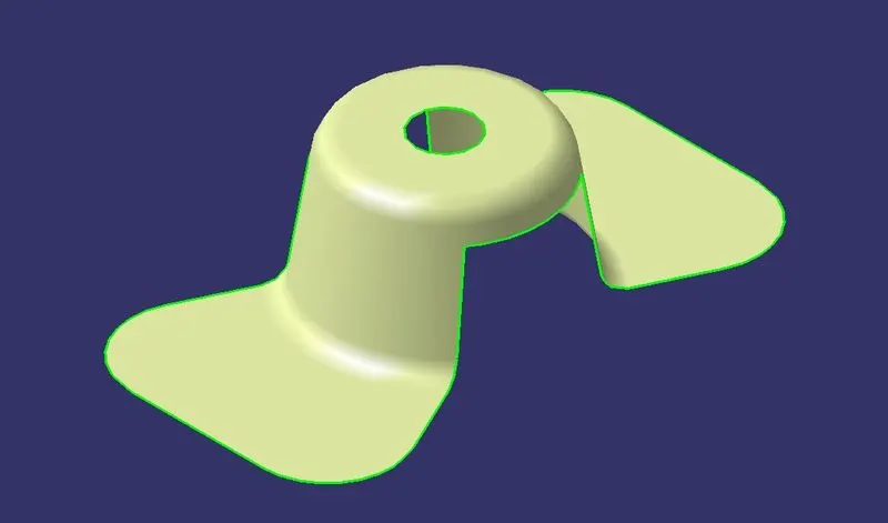
Step-1:
The tooling axis of our component is Z-Axis because our component has an upper hole, So its better to neglect Side core and our component in Z-axis.
*Our first step is to check in which direction the component is easy to move in the tooling direction.
*Took an Axis-System at the middle of the component for easy access.
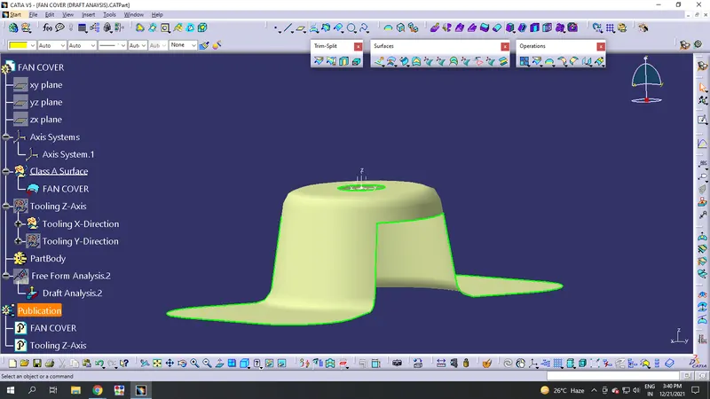
i. Along X-Direction:
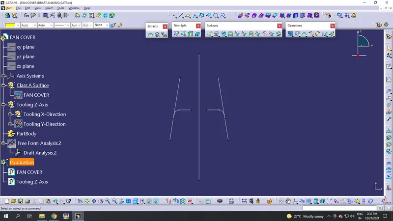
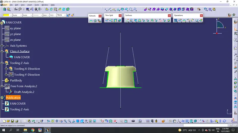
*So its not easy to manufacture in this direction.
ii. Along Y-Direction:
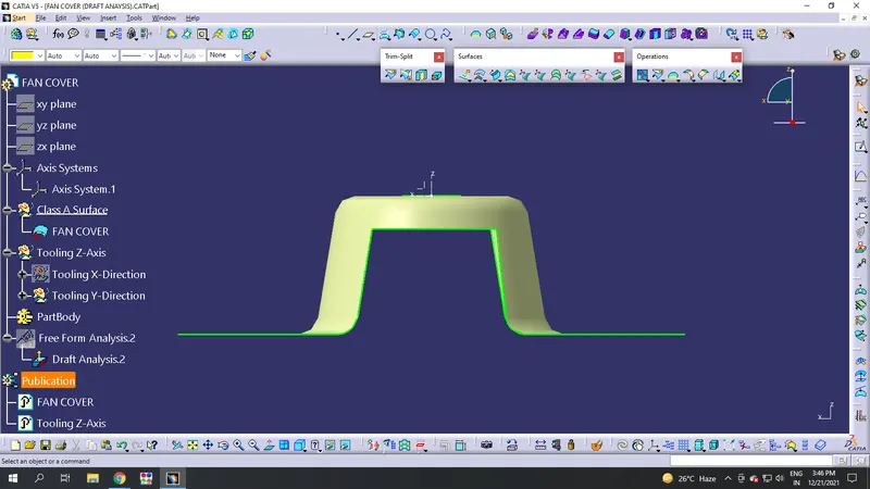
In this direction, its easy to take the total surfaces which are parallel to the axis.
Step-2:
*So, taking the intersection of the body which is intersecting the direction of Y.
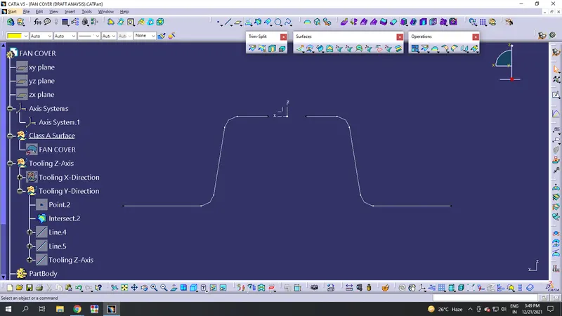
Step-3:
*To make it in bisecting method, I took a bisecting line for which the surfaces are parallel to the tooling axis.
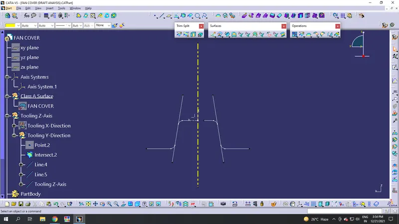
*Now we get a tooling axis for Draft Analysis to perform on the component.
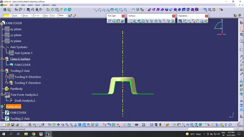
Step-4:
*Now Click on Insert>Analysis>Feature Draft Analysis. A menu appers for the Draft Analysis.
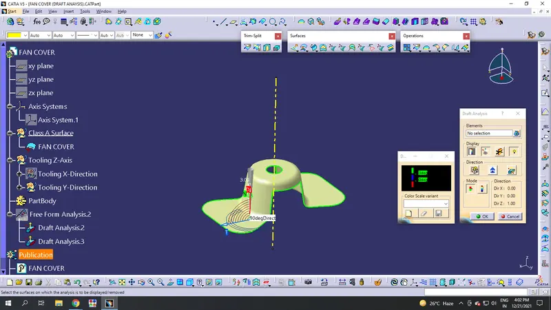
- Now Select the component for which the draft analysis should be done.
- Once selecting the element, choose the compass option on the top right and place it in the tooling axis and lock it in its correct position.
- After locking it, apply draft feature.
- After applying Draft, the complete object shows in green colour. When it showing green, the component is good at analysis and can manufacturable. When it shows you red colour, the component surfaces have a negative draft angle or zero draft angle. So, its better to edit and make it possible for manufacturing.
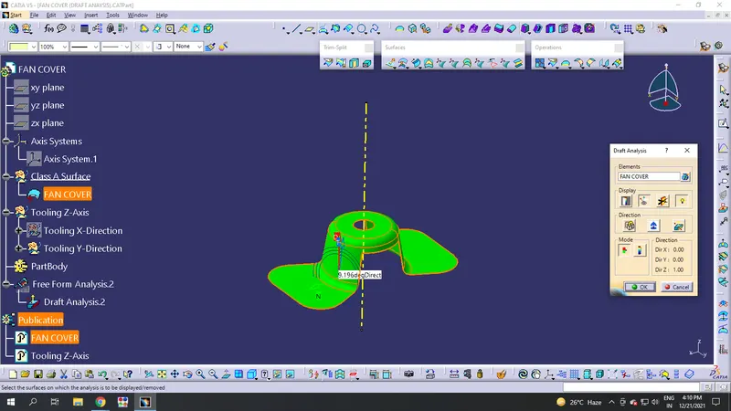
*Once you complete Draft analysis, publish the elements which you want to showcase it. Select it by Tools>Publication.
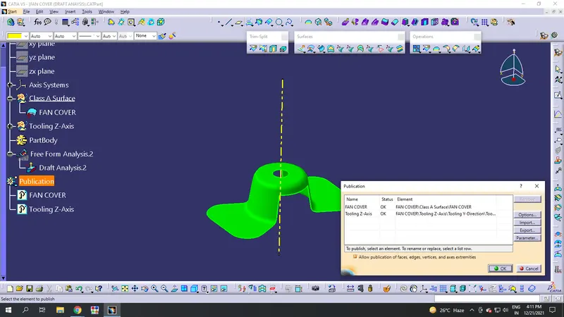
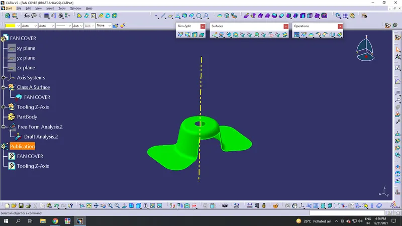
*Now the component has completed Draft Analysis and ready to manufacture.