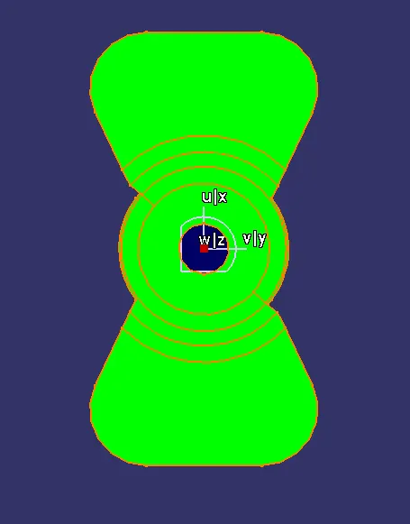
Week 8 - Challenge 1 - Draft Analysis on a Fan Cover
THE OBJECTIVE OF THIS ASSIGNMENT IS TO PERFORM DRAFT ANALYSIS ON THE GIVEN PART THAT IS A FAN COVER.
DRAFT ANALYSIS :
Draft is providing angles or tapers on the product features such as walls, ribs, posts anad bosses that lie parallel to the direction of release from the mold. It becomes difficult for the part which have straight 90 degree profile from its base. During molding after the part is cooled down the part tends to stick to the core of the mold as the property of the plastic is to get stick after it cools down. So if a part have straight 90 degree profile with the base then its get very difficult to eject the part as the whole part gets rubbed with the core and cavity during ejection which will reult in damaging the core, cavity and as well as the part due to rubbing friction through out the ejection process. But by giving a draft or taper we can simply avoid that and the part can easily get ejected. So it is a must or a design rule to give draft onto the components to ease the manufacturing process and avoid damage of components.
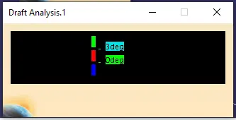
The minimum draft angle given on a plastic components is 3 degree and on sheet metal components is 7 degree.
The draft angle must be applied on both the inner and outer walls of the component.
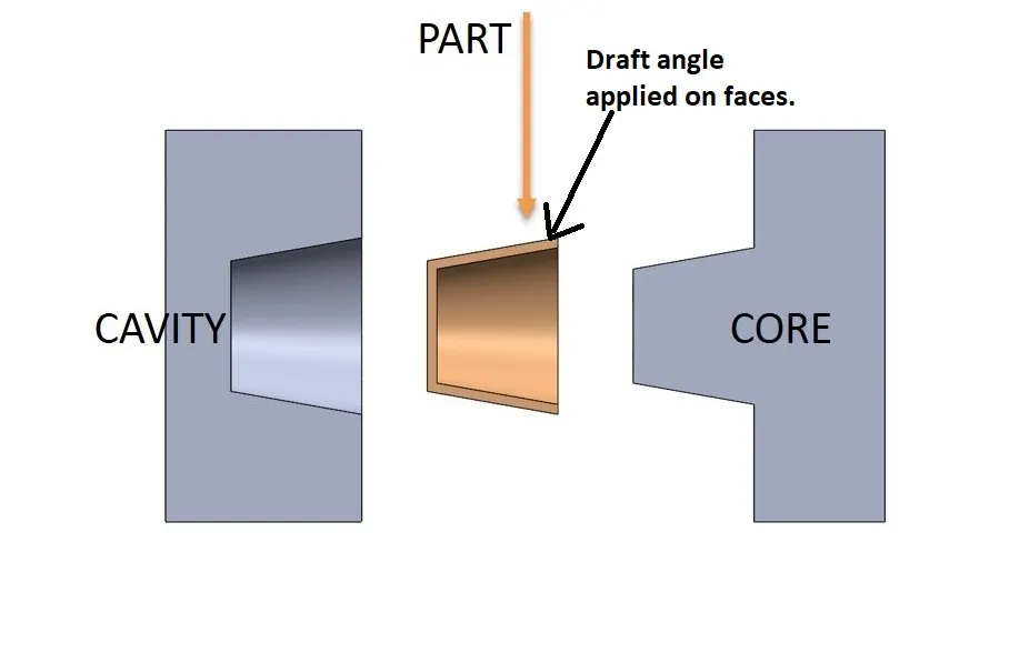
In order to check that proper draft angle is maintained in the component we perform DRAFT ANALYSIS.
And in the above assignment we performed draft analysis on a fan cover by creating a tooling axis by bisecting method.
In this method first we decide in which direction the part can be easily manufactured without increasing the manufacturing cost by avoiding side cores. After analyzing all the planes and direction we select a tooling direction.
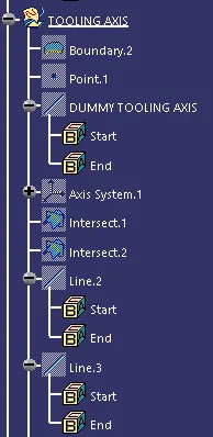
Then we create a point at the centre of the part and create the dummy tooling axis and a axis system for our reference.
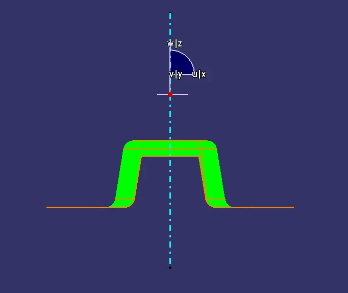
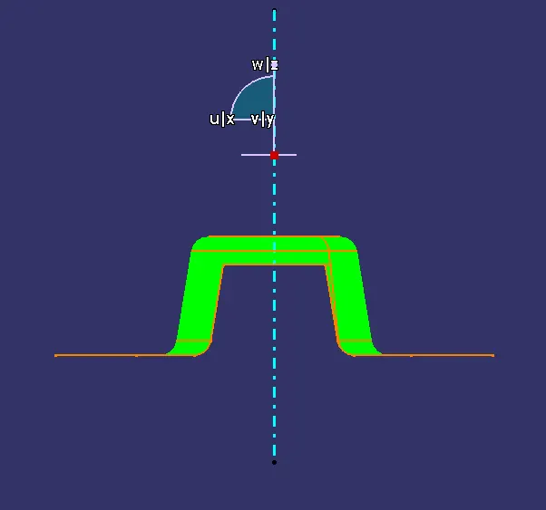
Then we intersect the part and the perpendicular planes to create the section of the part in order to find the faces that needs to have draft angle and create a bisecting lines between them in order to define our tooling axis.
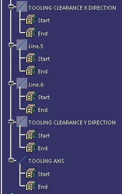
we have 2 planes perpendicular to the part and we get 2 intersecting sections and identified the faces that needs taper. After that we created lines following the taper profiles and these 2 lines gives a bisecting line.
The same procedure is performed for both the sections having taper profile and by doing so we get 2 bisecting lines from the 2 sections.
Then we create another bisecting line using the above 2 bisecting line which will be our TOOLING AXIS.
By following the above method we determined our TOOLING DIRECTION and created the TOOLING AXIS.
DRAFT ANALYSIS ON FAN COVER :
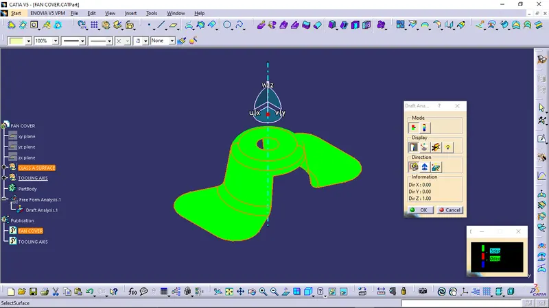
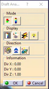
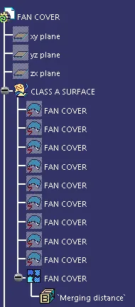
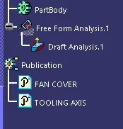
TREE STRUCTURE :
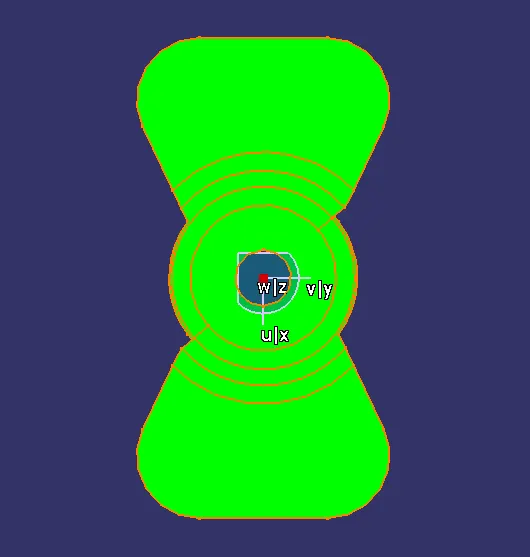
DIFFERENT VIEWS OF THE PART IN DRAFT ANALYSIS :
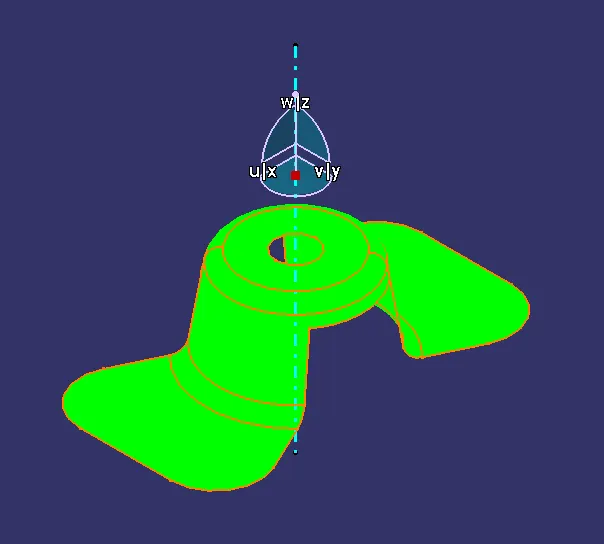
ISOMETRIC VIEW :
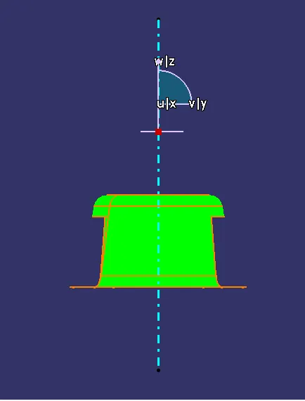
FRONT VIEW :
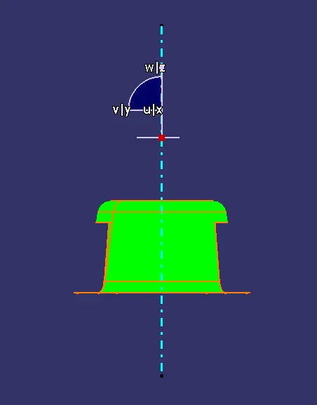
BACK VIEW :
LEFT VIEW :
RIGHT VIEW :
TOP VIEW :
BOTTOM VIEW :