Week 8 - Challenge 1 - Draft Analysis on a Fan Cover
Draft Analysis for Fan cover
Objective: The main objective of this project is to draft analysis by creating a tooling axis for a given Class-A surface.
Introduction
A small draft angle is provided to each and every area of components in order to get easy removal of the components from the tool. The draft analysis technique is used to analyze whether our part model created in cad is manufacturable based on the draft condition applied.
The major consideration of draft analysis is whether a sufficient draft angle is provided on the components. components while designing should be provided with a considerable amount of draft angle depending on the manufacturing consideration. For plastic components provide a draft angle of 3 degrees ( draft angle of 0.5 is given ideally to the feature inside the plastic part). But for automotive sheet metal s, it will be from 7 degrees or more.
Tooling direction
In molding, machine arrangement is given to open the mold along a direction which is known as tooling direction.
Producer
Class- A surface
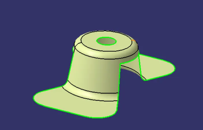
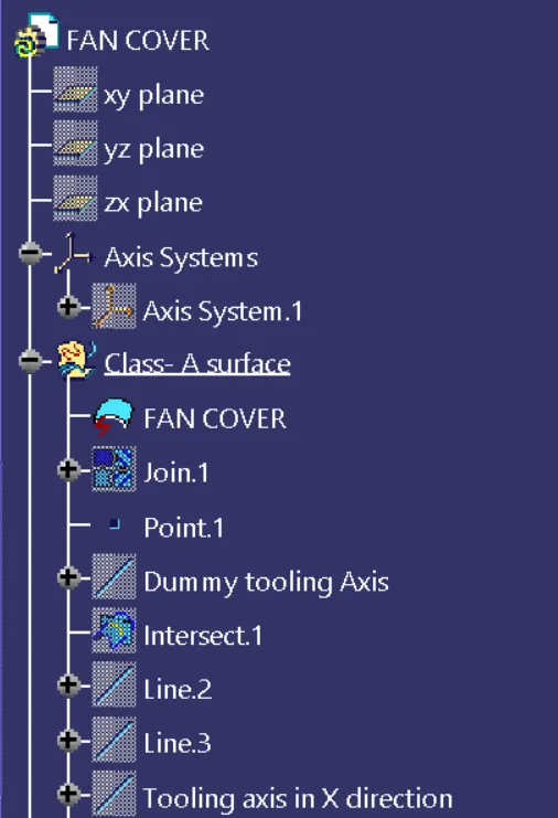
1. Firstly the given stylish surface was imported into Catia, then check whether the irregularities by using a command as join, Boundary, and disassemble.
2. Create a center point in the given class A surface in the center hole by using the ellipses/circle option.
3. Then a dummy axis was created on the center point in Z-direction.
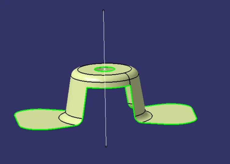
4. Create an Axis system on the center point, select the ZX plane to create a tooling axis in the X-direction.
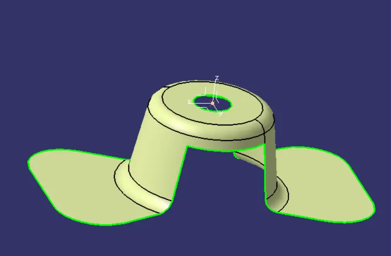
5. By selecting the Intersection curve command, select a point to point line to extend the line then select bisecting line used between that two-line along an X-direction.
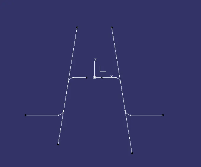
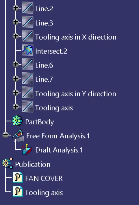
6. In a similar way select the ZY plane on the axis system by intersection curve command on the zy direction, then select the two-line by point to point line to extend the line bisecting line command is created between two lines along the Y direction.
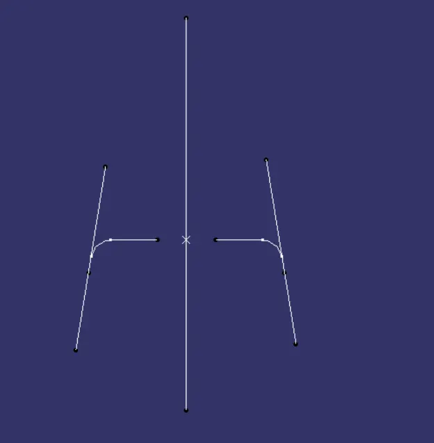
7. Finally by selecting two tooling axis as created in the X and Y direction by bisecting line command select two-axis lines to get the finally tooling axis as in the Z direction.
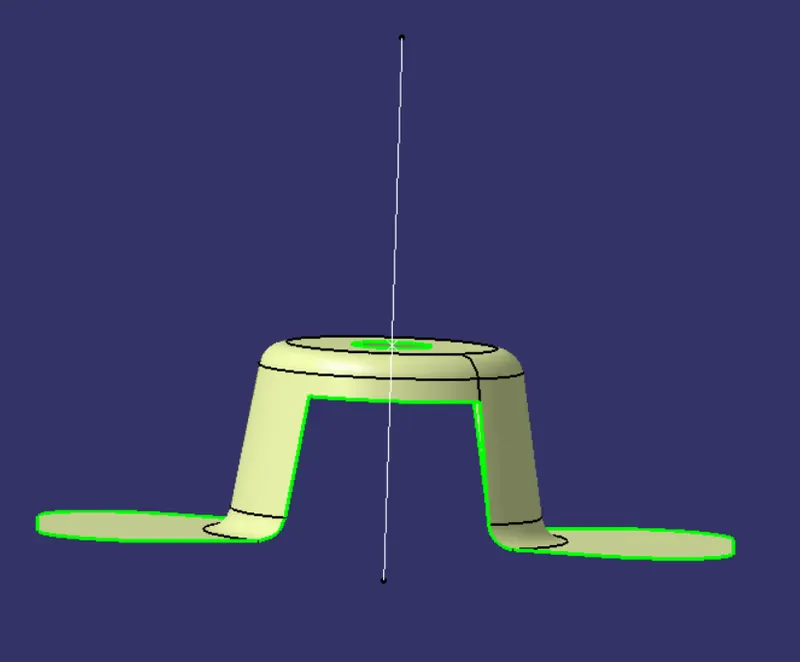
Draft Analysis
For draft, analysis selects a customize view parameter in that select a material condition -ok, then Insert- analysis- Feature draft analysis.
1. For the plastic part the nominal angle value for draft analysis is 3 degrees but even a 0.5-degree angle can be created for sub-assemblies like ribs, slots. for automotive sheet metal, the nomial draft angle is 7 degrees.
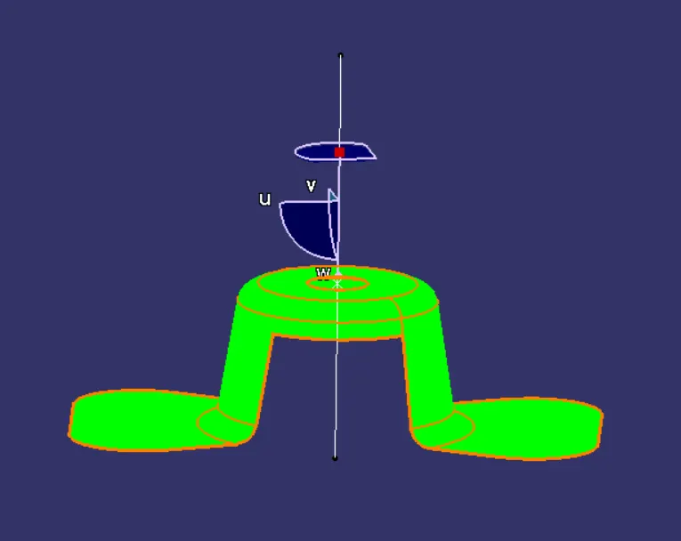
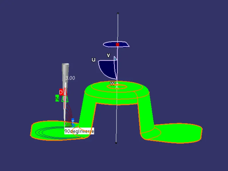
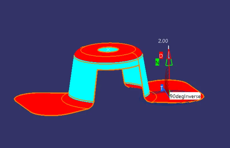
2. Draft analysis was carried out by pulling the compass to the tooling direction and an inverse draft axis was created if required.
3. After setting a compass on the tooling axis the compass must be locked to a specific direction.
4. If the class A surface shows green colour then the model passes or else further operations need to be carried out.
5. Also here we get full analysis mode detailed analysis can be carried out for complicated assemblies. by using running point complicated parts and surface were checked in detail.
Publication
Tooling axis in the Z direction and Class A surface were published for further easy reference, from Tool-Publication
Conclusion
Thus the draft analysis for fan cover was carried the perfect tooling direction and the given Class-A surface was ready to move on for further operations.