Week 8 - Challenge 1 - Draft Analysis on a Fan Cover
DRAFT ANALYSIS ON FAN COVER CLASS A PART
Objectives:
- Understand the surface geometries of the given part to interpret the molding process.
- To generate a proper tooling axis for the part.
- Conduct draft analysis on the model to analyze the moldability.
Software used: DS CATIA P3 V5 - GENERATIVE SHAPE DESIGN WORKBENCH
Introduction: Molding is one of the most important procedures for the product lifecycle in the automotive industry. In the case of plastic injection molding, Proper design and construction of the core and cavity must be ensured before starting the process. When designing the product using 3d modeling software, An engineer should check not only aesthetics and functionality, but also the ability to manufacture the component with minimal requirement of material, time, cost, and energy without any compromises in quality. Software like CATIA has inbuilt tools to analyze whether the product design is good to produce or not. There comes the role of the Draft analysis.
Draft analysis: Drafts are a type of modification that is usually given to product design for the application of manufacturing. It ensures proper removal of the product of the molding process without sticking to the core and cavity. For this, we provide slanted edges at the sides of the product being designed. In CATIA, we have a tool called draft analysis to check if the product is feasible enough for the molding process. It checks every edges and slanted surfaces for draft angles and gives output as shifting in coloures where the draft angles are accepted or not.
Methodology for finding the tooling axis:
Step 1: Surface continuity check
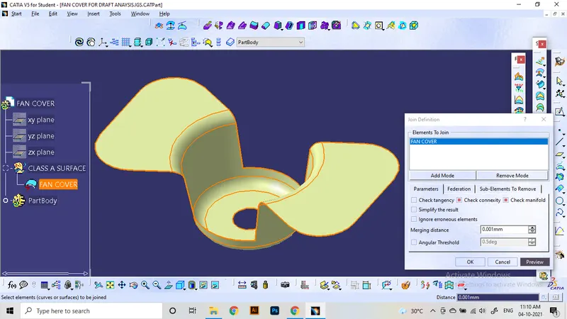
It is done to find out all the edges or ends of the required geometrical data are joined with the right surfaces as required, ensuring there is no gap between 2 surfaces. We can use join or boundary command to visualize the edges of the part. It will show if there are any opened edges or misaligned, non-continuous surfaces. The Boundary command will check the model and show only the boundary edges.
Step 2: Generating the main tooling axis using Bisector lines:
Tooling axis is the direction in which the mold core and cavity opens or closes. The alignment of the tooling axis will be depended on the form of part to be manufactured. Analyzing the design helps to identify the best area to provide tooling axis with minimum or no requirements of other functionalities like side cores.
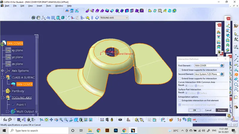
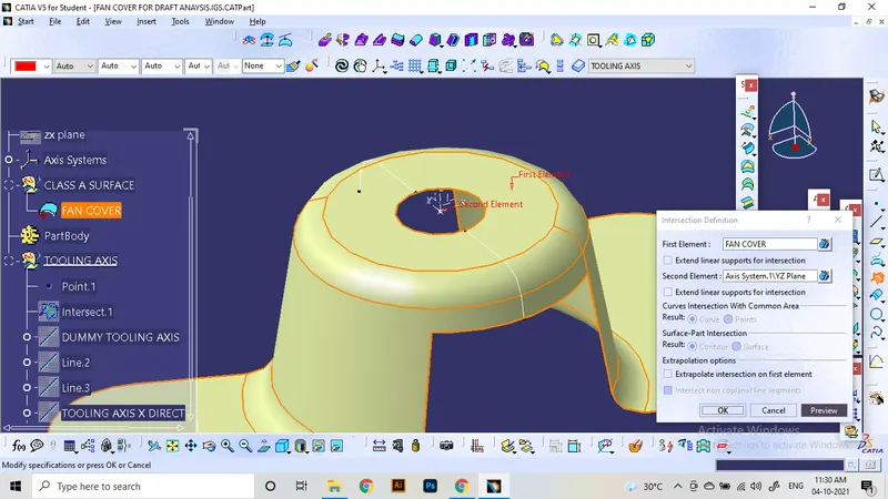
For the given model we need to identify the tooling axis corresponding to X and Y direction to determine the main tooling axis. For that, I'm adding an axis system on top of the part. It will be used to divide the part into symmetrical segments in x and y direction.
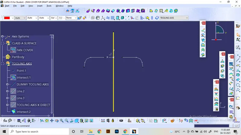
Here is the intersection process at ZX plain.
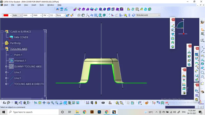
By referring the side views of the intersection lines, we can see the surface flow properly. To determine the Tooling axis in X direction, we need to get the centerline passing through the middle point of these lines. It can be done using the Bisecting line tool. Before that, we make a 'dummy tooling axis' through the center of the hole as marked in yellow.
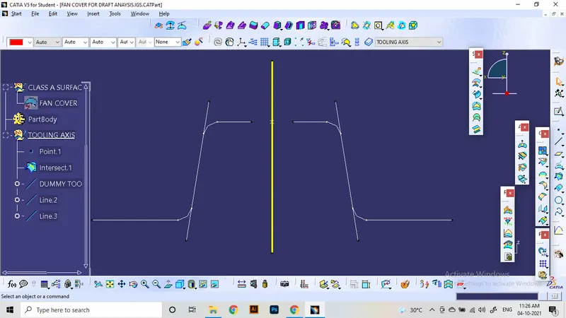
For the tooling axis to be properly made, we use bisection of the two slanted lines as the other faces are perpendicular to the dummy axis. Use the bisecting command in the line definition toolbox for bisecting these lines. for the point, assign the middle point of the circle as shown.
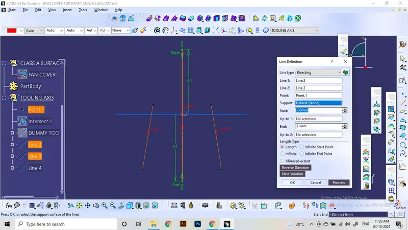
The resulting bisector line is considered as the main tooling axis.
Repeat these steps by starting with intersection along YZ plain to Create the Tooling axis in Y direction. Here, there is only a small length is available for the slanted faces. we should extend them using point to point line command.
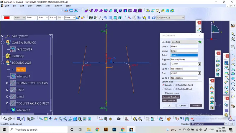
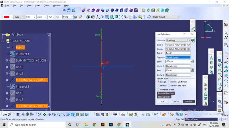
Now we have got the two tooling axes.
Bisecting Again between these two Axes gives the Main tooling axis (marked in red). Since the design is properly symmetrical, The 3 tooling Axes are generated along the same line.
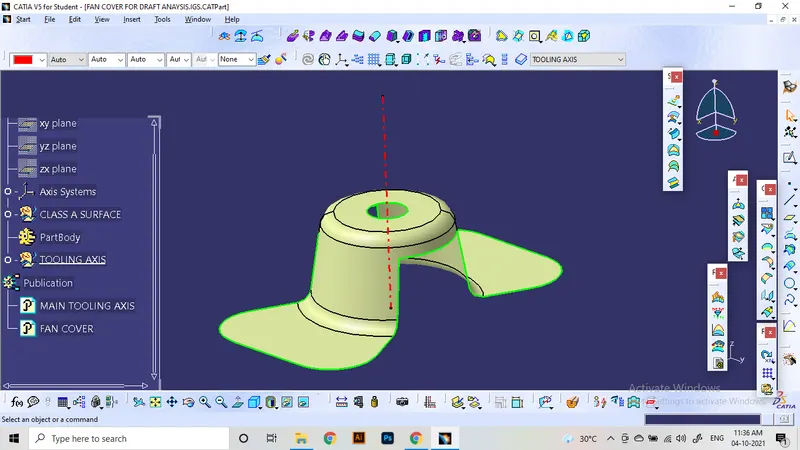
step 3: Publishing
After determining the tooling axis, we can publish the class A surface and tooling axis using tools -> Publication.
draft analysis:-
In catia, The result of this analysis is produced as colored Visualization. For conducting the draft analysis, use the tool, Insert->Analysis->Feature draft analysis or click the corresponding icon at toolbar.
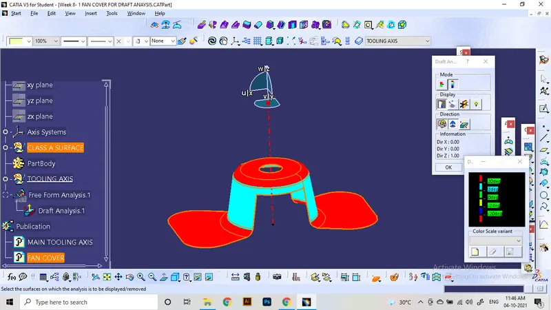
The first symbol showing is for the quick analysis option, it is used to check quickly for the given value of the draft angle if provided on the design. initially, we need to enable the compass in the direction tab to set the direction of the tooling axis. Move the compass to the tooling axis by picking the red dot and align it to the tooling axis where, the w direction of compass comes inline to the axis.
Normally, Clicking the part will show the color green where draft angle is ok and red if the angle is 0, and blue if the angle is negative. we can change the color and the value of draft angle to be checked in the window shown below the draft analysis toolbox. To enable or disable the color scale, use the first tool in display tab.
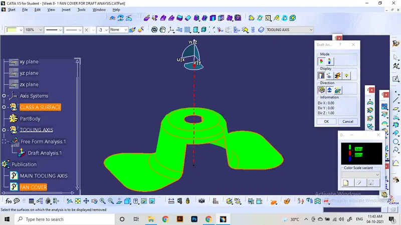
The second tool in the display tab is used to analyze the draft angle at the regions where the moves pointer moves. Can use it to measure the angle of every surfaces.
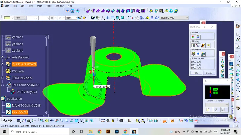
Third tool in display shows and hides the highlights at the surface edges and the last tool changes the lighting to enable or disable shading.
Last tool in the direction tab inverses the tooling direction.
Second mode in the draft analysis is used to conduct full analysis. In this mode, the analysis shows multiple color options on different value ranges of draft angles. These can also be altered in the color scale toolbox. It is used for advanced visualization of draft analysis.