Week 8 - Challenge 1 - Base Bracket Design
BASE BRACKET DESIGN:
Base bracket design from given Class A surface includes the following steps-
1. Tooling axis
2. Draft analysis of Class A
3. Class B surface
4. Class C surface
5. Solid body
6. Draft analysis of solid body
Tooling axis (by perpendicular to part): -
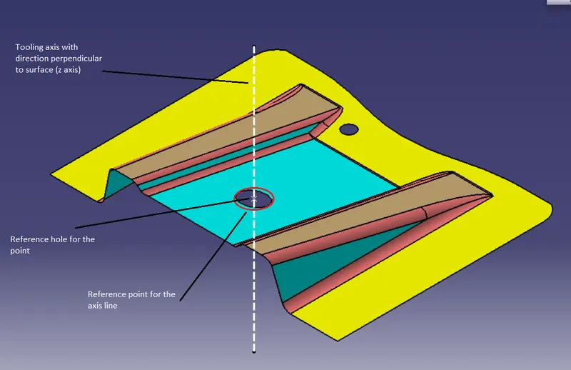
In this method, the direction of tooling axis can be inferred by visually observing the part and selecting the reference axis or direction perpendicular to it. This method for creating axis can be used for small and simple parts but not for complex parts.
First a point is created for the axis using the hole, the direction perpendicular to the hole is selected for the ejection direction or tooling axis direction.
Tooling axis (by bisecting method): -
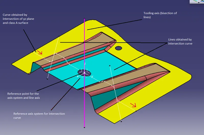
In this method, the tooling axis is created by the use of lines which belong to the surface. First an axis system is inserted using a reference point. The point is the center of the hole. Here the hole which is at the base cannot be selected due to absence of inclined surfaces which can be used for creating the lines. The intersection command creates the intersection between the surface and the yz plane. Then the two lines can be created using the vertices which are generated with the use of intersection command. The lines representing the inclined surface of both sides are creating by the point-to-point line command. Then the tooling axis which is bisecting both lines is created.
Class B surface: -
Creating Class B surface and solid body is not possible with thick surface and offsetting the surface as these commands will not give the desired results for this surface.
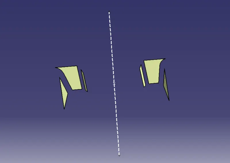
Thus, the faces have to be selected individually, extracted and untrimmed to turn them into planes. These planes are then extrapolated and trimmed and the result is then offsetted for a thickness of 2.5mm. Thus, Class B surface is generated.
Extract
Untrim
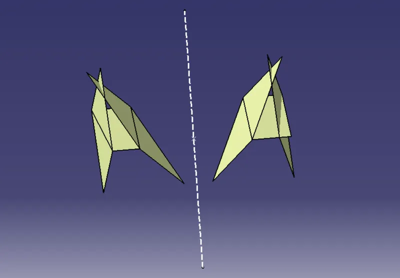
Extrapolate
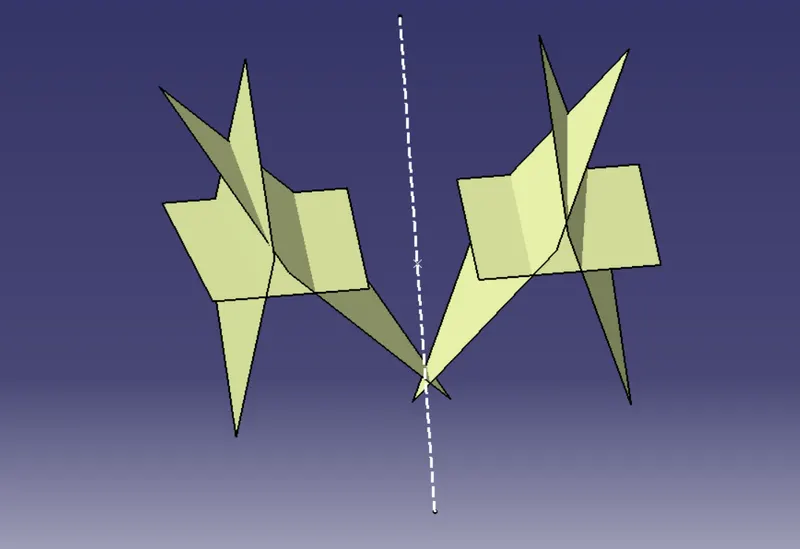
Trim and offset
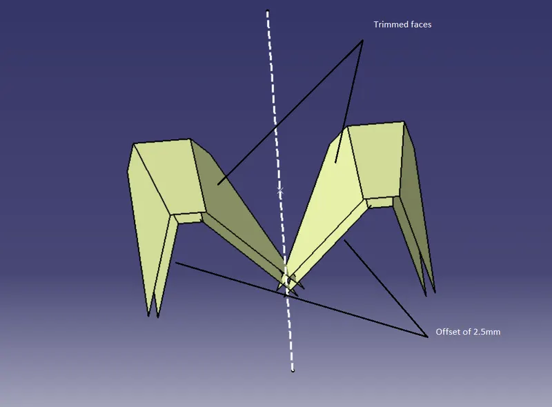
Class B
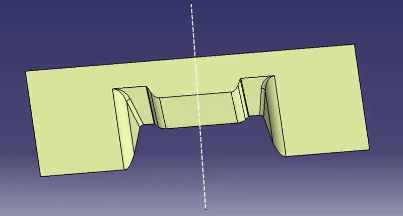
Class C surface: -
For Class C the boundary of Class A is selected using the boundary command and the boundary curve is obtained. The boundary curve is extruded perpendicular to the Class A surface using the sweep command. Using this command, an inclination is also possible to give to the surface. Similarly, the holes for the part are also created but their inclination is opposite to the inclination given to the outer boundary surface.
The surface for the solid part is generated by trimming first Class A and Class C surfaces and then Class B surface. The solid component is created using the close surface command.
Boundary
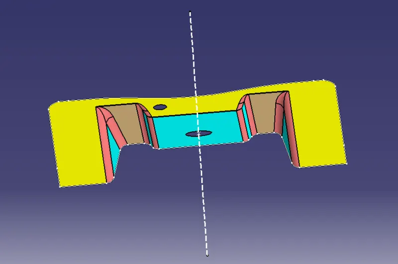
Sweep
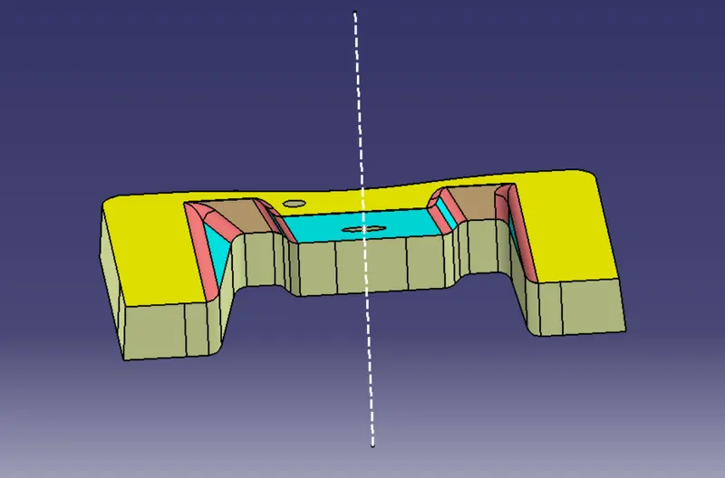
Solid body by trim of Class A, Class B and Class C
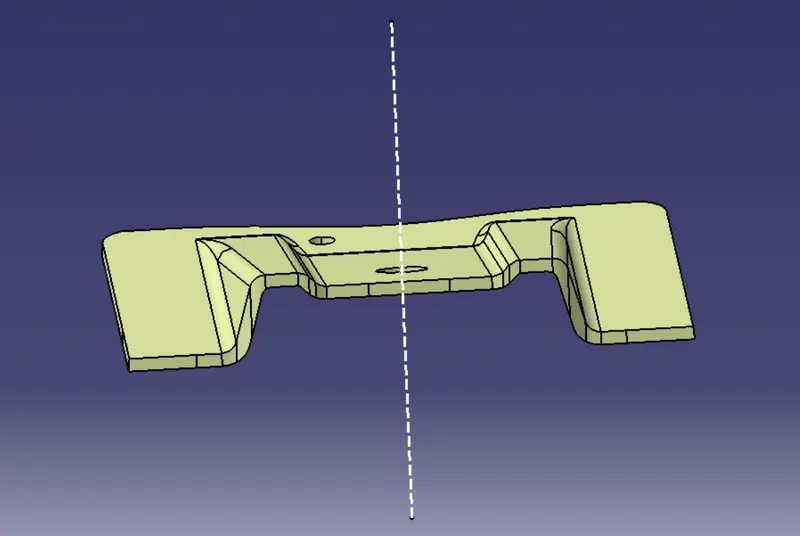
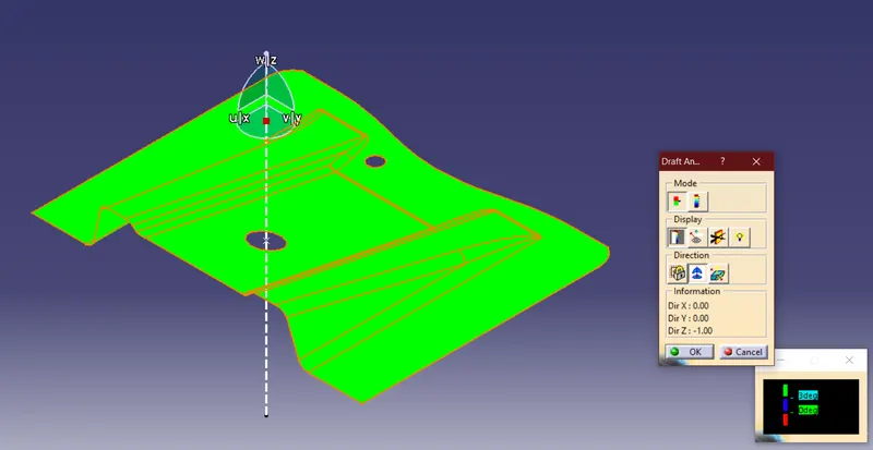
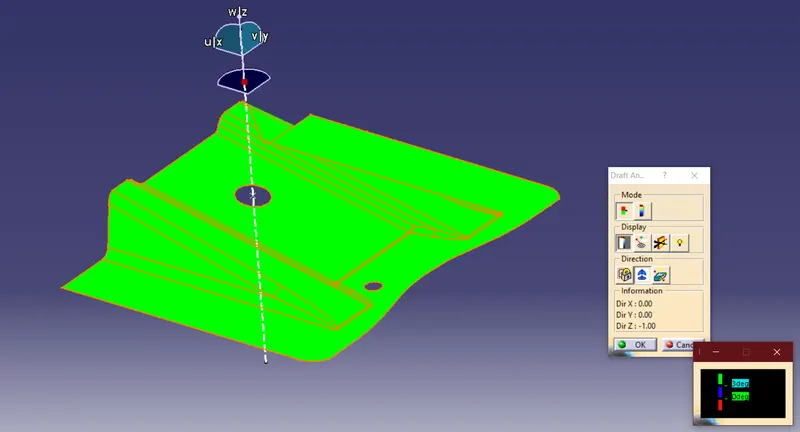
Class A draft analysis: -
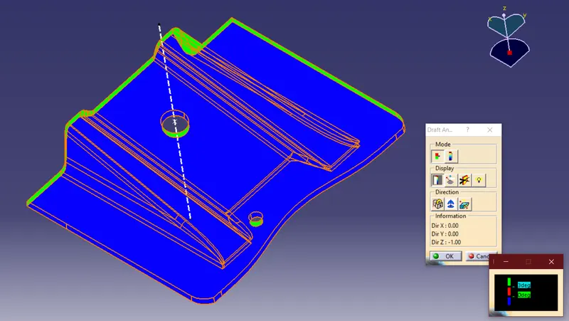
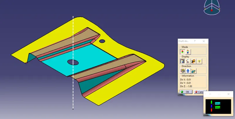
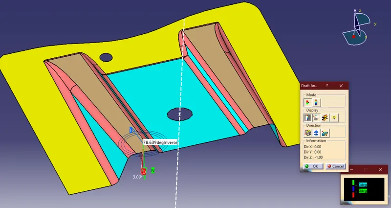
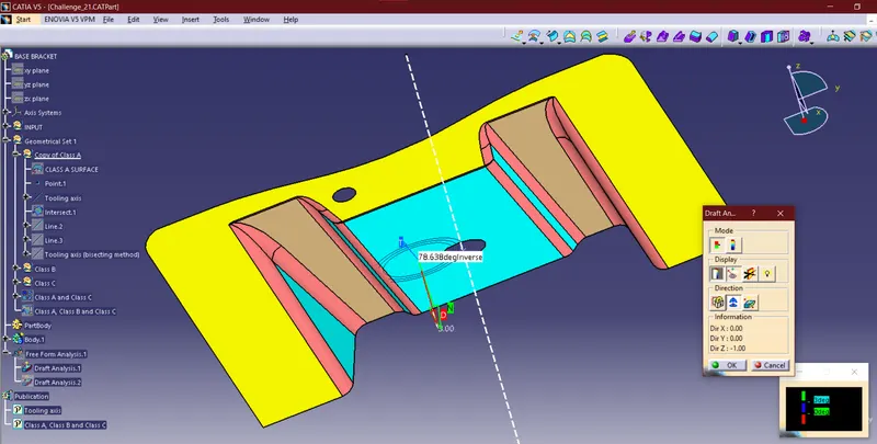
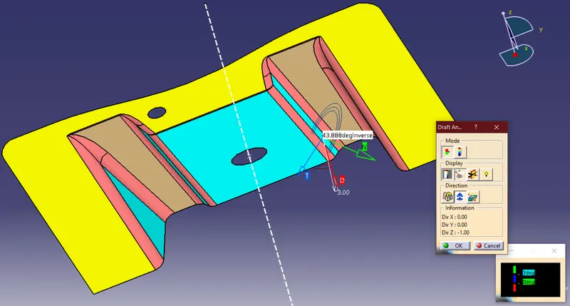
The tooling axis is created at the center of the hole on the center surface and in the z direction. In customize view parameters in the shading section material is selected. The draft analysis tool is inserted using the insert section.
Using the compass option, the compass is positioned and adjusted on the tooling axis of the surface. After that colour code is changed according to requirement. For this case, 3-degree draft is selected as the higher limit with green colour and zero draft as the lower limit with blue colour. Red colour is assigned to the negative draft, for the ejection to be performed without undercuts, the value of draft cannot be negative.
Plastic part draft analysis: -
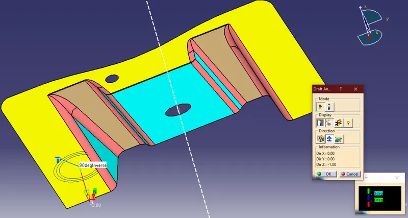
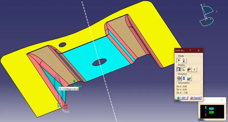
The tooling axis is same as the Class A surface. The analysis parameters are the same as the Class A draft analysis. The compass is again positioned and adjusted as in the previous analysis and the final part is selected for analysis.
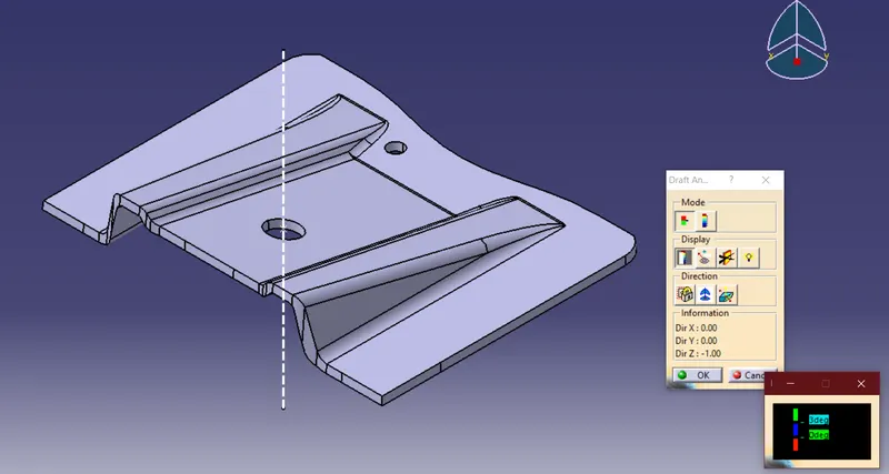
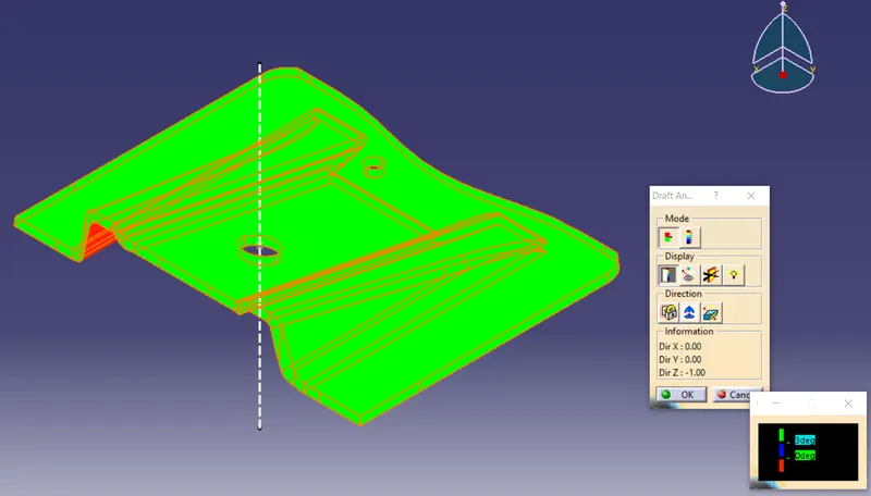
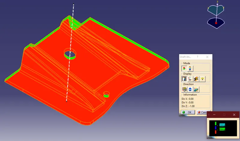
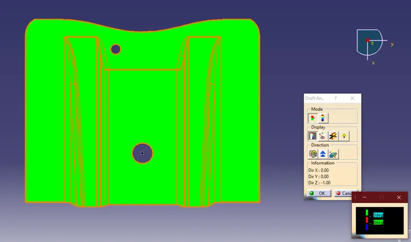
The results show that Class A and Class C surfaces have draft angle higher than 3-degrees and thus are acceptable. However, the Class B surface is not acceptable due to the drat angle shown negative by the draft analysis. To resolve this error let us check the values of angles of Class B faces along with faces of Class A.
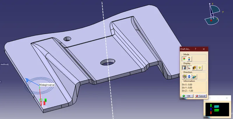
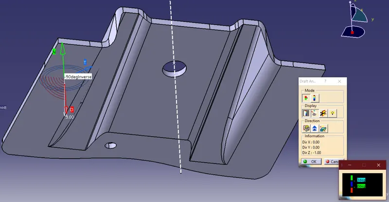
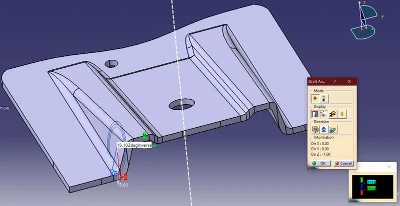
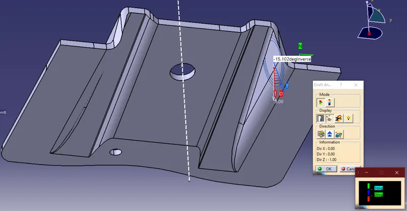
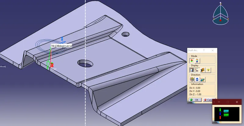
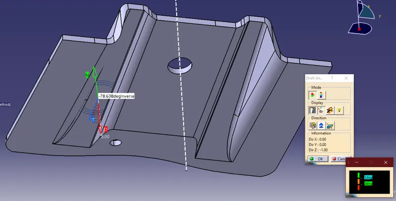
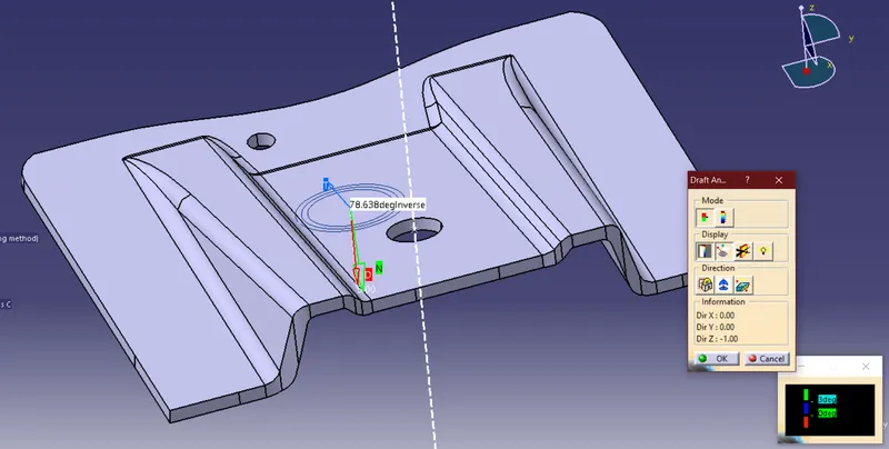
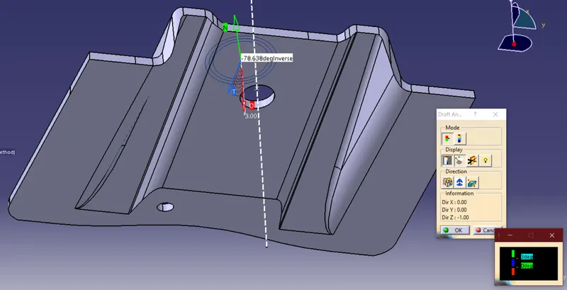
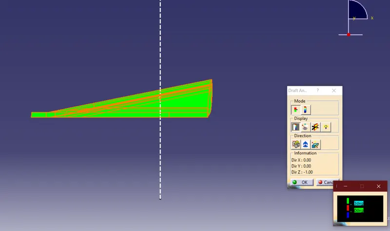
By observing and comparing all the draft angles of the respective faces of Class A and Class B, it can be inferred that the values of angles of Class A and Class B are same and of opposite sign to each other. Thus. the draft analysis shows Class B red or the draft of Class B as negative due to the direction of the normal of the surface which is opposite of that of Class A and draft direction. Thus, the ejection of the final plastic component can be done easily without the problem of undercuts.
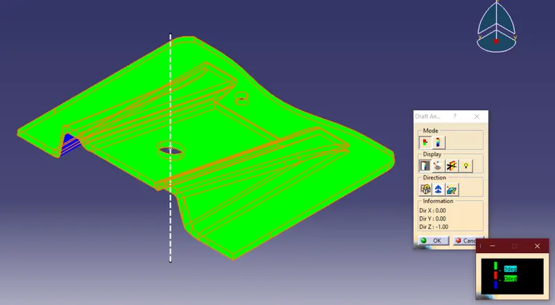
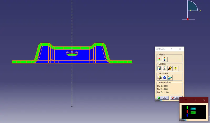
The colour code is changed to show that Class B is acceptable for the draft analysis. Various orientations of the part are given below with the changed colour code.
Isometric view
Front view
Top view
Left side view
Class B view