Week 8 - Challenge 1 - Base Bracket Design
OBJECTIVE:
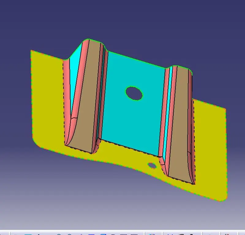
Create the Base Bracket Plastic component through the given Class-A surface. To begin with, the tooling axis for the given Class-A Surface should be created meeting the requirements of the draft angle and at the end perform the Draft analysis on the model.
REQUIREMENTS:
Software Knowledge about CATIA V5.
PROCEDURE
Open the given class A surface file.
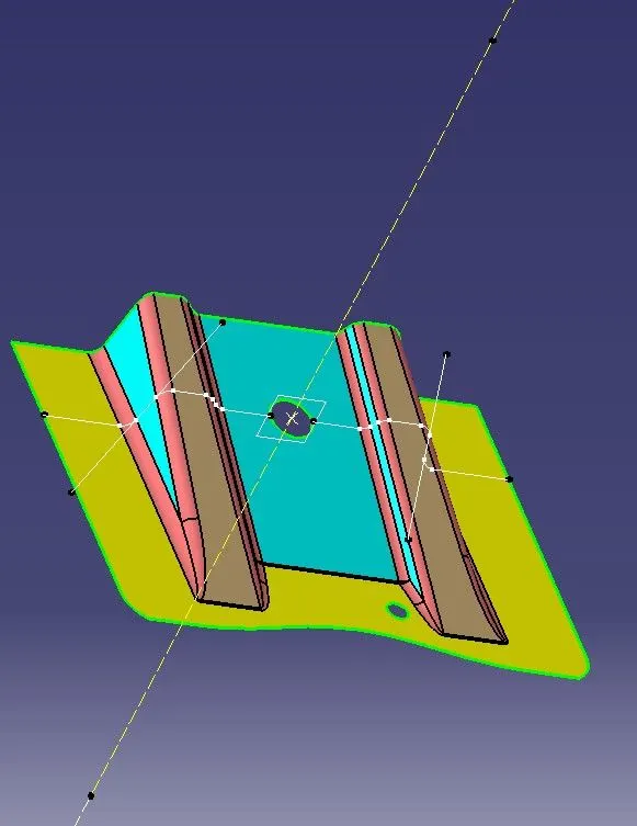
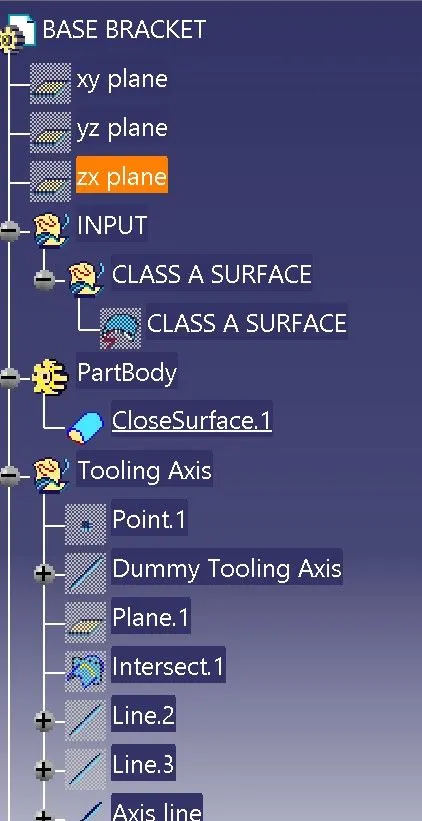
To create the "Tooling Axis" for the component, we must carefully examine and analyse the class A surface, and the base bracket Z-axis is the best option. By using the reference point established in the centre of the circle as a starting point, I first generated a mock tooling axis on the Z-axis.
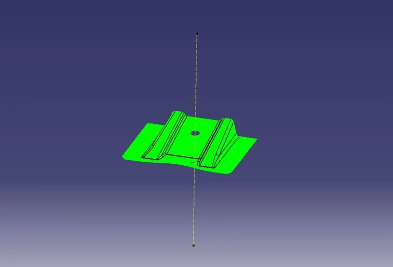
DRAFT ANALYSIS OF CLASS A SURFACE
To perform draft analysis, click on Insert >>Analysis >> Feature Draft Analysis.
To examine the angle for various sides (ribs and inclined plane angles) on the class A surface, open the draught analysis toolbar, navigate to the display block, and choose the "Analysis under the running point" command. The colours Green, Blue, and Red on the colour scale at the bottom show whether the draught angle (3 degrees) satisfies the standards or not. We must align and fix the compass to the tooling axis of the class A surface when the draught angle analysis is complete.
CLASS B SURFACE
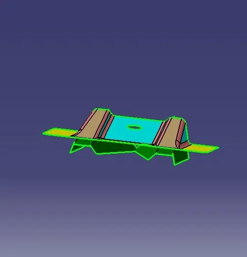
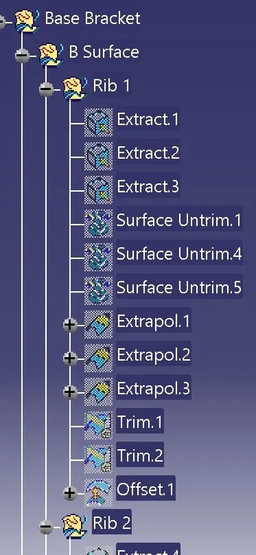
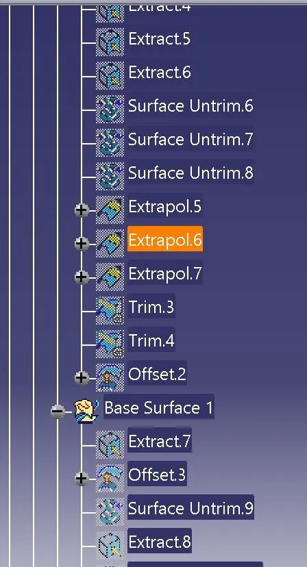
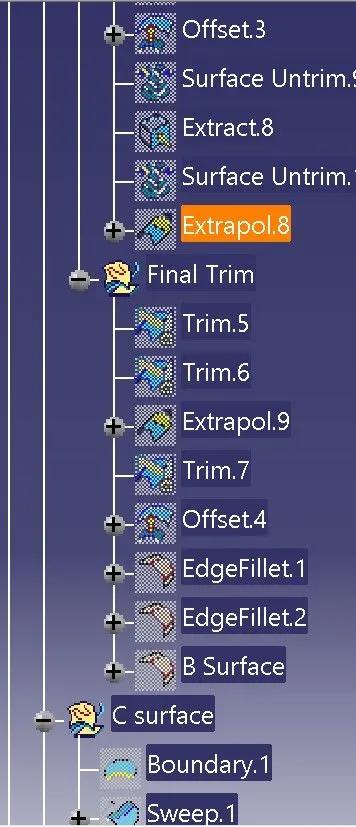
I divided the surface's three components—Rib-1, Rib-2, and Base surface—into three to form the class B surface. To avoid mistakes, we must extract the surfaces, untrim the extracted surfaces, then extrapolate those untrimmed surfaces with point continuity. Fillets may result in an error if we immediately offset the class A surface. Now, shape the extrapolated surfaces to your specifications. Fillets were then provided to the final trim.
CLASS C SURFACE
It combines elements from classes A and B. I utilised the sweep command, taking into account the class A surface's outside boundary, to build a class C surface. Go to the "line" command in the "profile" block of the sweep command; the subtype is "with draught direction." To sweep, choose the inside down arrow since the class B surface is below the class A surface in this situation. Next, choose the outer boundary and tooling axis. The draught angle for a plastic component is 0.5 to 3 deg. The two circles on the class A surface go through the same process twice.
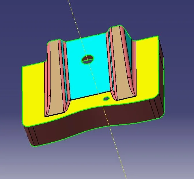
FINAL OUTPUT
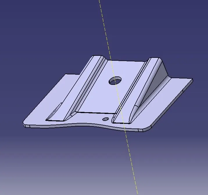
Using the "join" command, I joined all of the swept surfaces at this point. I then cut the Class A, Class B, and Class C surfaces to create a closed surface, which created a Solid body.
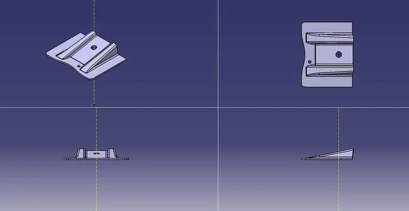
DRAFT ANALYSIS FOR FINAL OUTPUT
Go to the Direction block in the draf analysis toolbar and select the "Use the compass to set the new current draft direction" option to align and fix the compass to the tooling axis (or just click on the compass symbol). Bring the compass to the surface at this point, align it with the class A surface's tooling axis, and then click the lock icon next to it in the direction block. We can complete the draught analysis process by clicking "ok" on the toolbar for draft analysis.
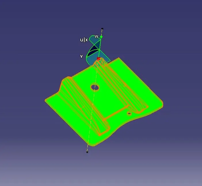
The Minimum Draft angle 0.5 was given to the final out come and it has passed without any errors.
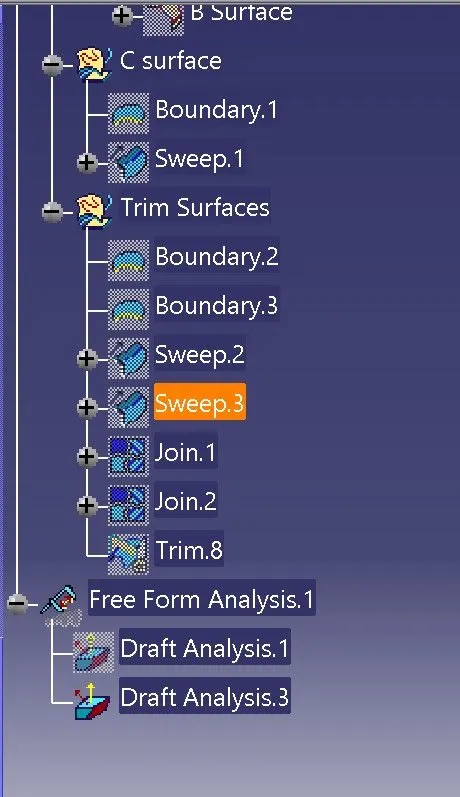
FEATURE TREE FOR MODEL
CONCLUSION
Thus the Base Bracket Plastic component through the given Class-A surface is completed, the tooling axis for the given Class-A Surface is created, meeting the requirements of the draft angle.