Week 8 - Challenge 1 - Base Bracket Design
Aim: To create a Base Bracket Plastic Component through a given Class A Surface and perform Draft Analysis on the final plastic component.
Objectives:
- Creation of Tooling Axis.
- Creation of Class B and Class C surface.
- Creating a solid part out of surface modelling.
- Draft Analysis of Class A surface and final plastic component.
Tool Used: CATIA V5
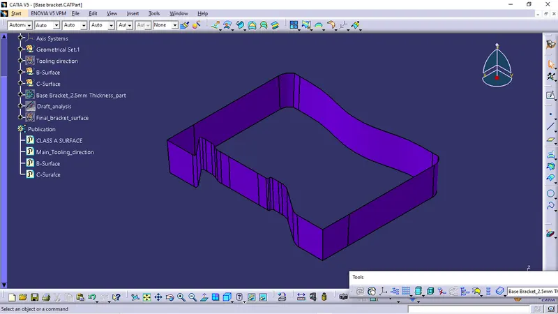
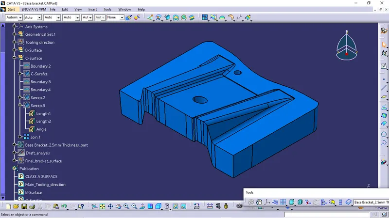
Introduction: In this project we are designing a base bracket using given class A surface. The approach includes creation of Class 'B' surface keeping 2.5 mm thickness in mind for the complete component. The design also included Class 'C' creation from the given parent surface.
Constraints:
- NO CHANGES IN CLASS 'A' ARE ALLOWED.
- ALL DESIGN RULES SHOULD BE STRICTLY FOLLOWED.
- ALL SURFACES SHOULD BE CLOSED BEFORE CONVERTING TO SOLID.
- ALL FACES SHOULD MEET THE ALLOWED DRAFT REQUIREMENTS.
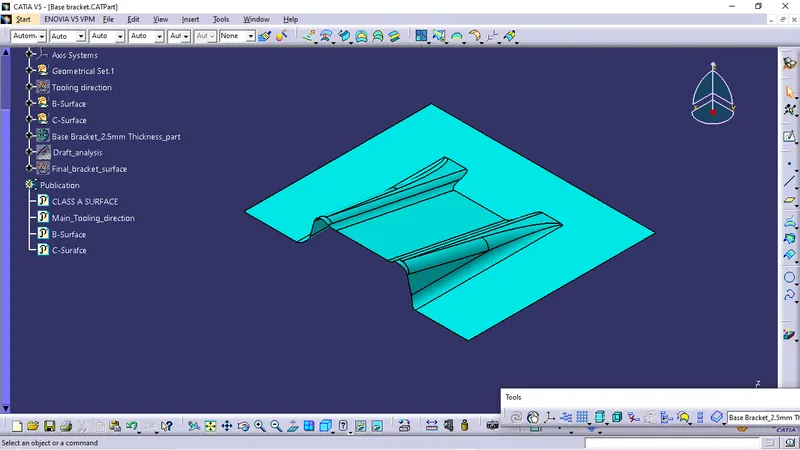
CLASS A: Following surface is given as the input for the component creation.
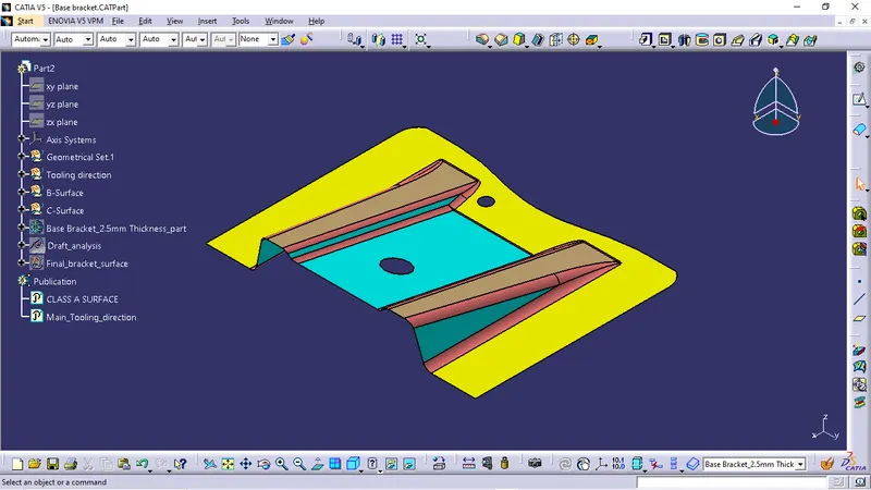
To continue with the design process first we need to find out the tooling axis for the surface and check for all the drafts using Draft Analysis tool of CATIA.
Creating of Tooling Axis:
- Tooling axis : The direction in which the core and cavity (or) mould opens.
- Depending on tooling axis the component is designed which will be easy to manufacture the mould and produce the component with no deviations.
- Creating a tooling axis is as important as component .
- Tooling axis can be defined visually which is not acceptable. But we can define tooling axis through the planes and creating some lines according to surfaces.
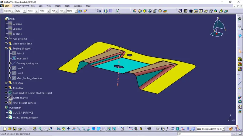
Pink center line is the dummy tooling axis
- According to the given surface we created the dummy tooling axis which will be approximately equal to the main tooling axis.
- After that we created the intersection curves along Z direction.
- Assuming this as a tooling axis and check all the parallel and perpendicular surfaces.
- Now create a intersection curves to the parallel walls of tooling axis.
- Create two lines along those parallel walls and bisect those two lines.
- Hence the bisect line is the Main tooling axis.
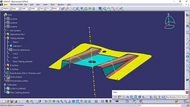
Yellow centre line is the Main tooling axis
Class 'A' Surface :
Class 'B' Surface :
Class 'C' Surface :
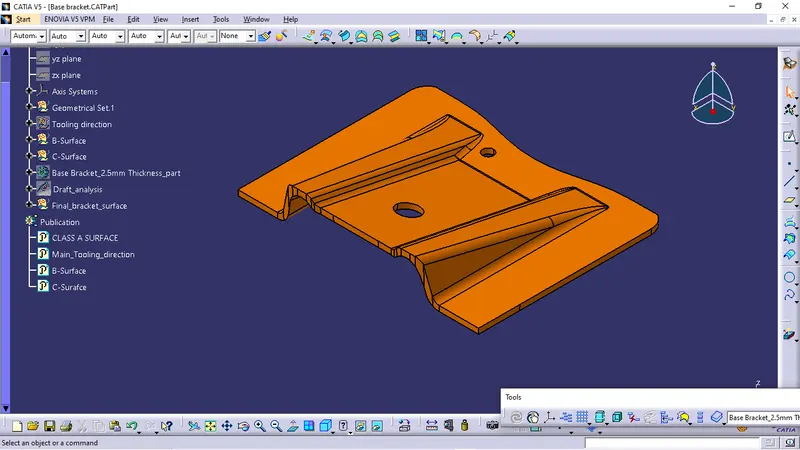
Final trims:
Class A + Class B
Class A + Class B + Class C
Publication : It is used to make easily accessible of the published components.
Draft Analysis :
- The draft analysis technique is used to analyze whether our part model created in CAD is manufacturable based on the draft condition applied. Here the part should get easily removed from the Mold.
- No parts can be ejected from the tool if it is having a straight 90-degree profile from its base surface. A small draft angle is provided to each and every area of the component in order to get easy removal of the component from the tool.
- Here we are providing a direction in which components should eject in order to get easy removal of components from the tool. In other words, it also lets us know whether the model is having a draft angle and how much is the draft angle from the tool direction.
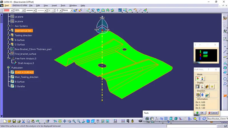
- Here we done draft analysis using tooling direction with a draft angle 3degree.
- All the surfaces should show green in colour when draft analysis is done. Then only it is perfect to go as per the draft condition.