Week 8 - Challenge 1 - Base Bracket Design
Draft analysis: Draft is the angle at which the part is tapered, allowing it to release from the mold. As the part cools it tends to shrink and gets attached to the walls of the mold. Adding this draft angle helps to remove the part easily from the mold.
Most parts require a minimum of 1/2 to 1 degree of draft angle, however, 3 degrees is a widely accepted norm. 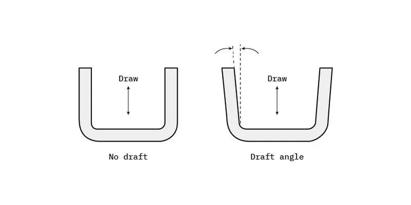
From the given class-A surface we need to extract a body of thickness of 3mm with a draft angle of 3degree. The given class-A surface is not uniform so we cannot perform the thicken operation. The approach to get our desired part is, we extract each and every individual part of the surface, untrim it and then offset the final outcome to a distance of 3 mm.
The steps are as follows:
given class-A surface
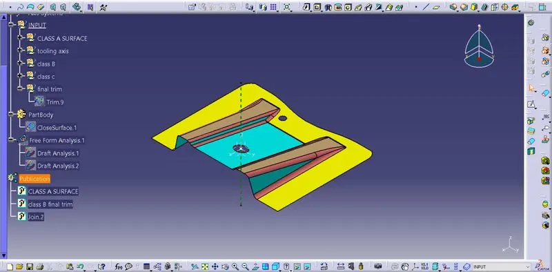
Select the class-A surface and use the join command, if there are edges that are not connected, after joining the entire surface gets updated without any gaps. This Joined surface will be our working part.
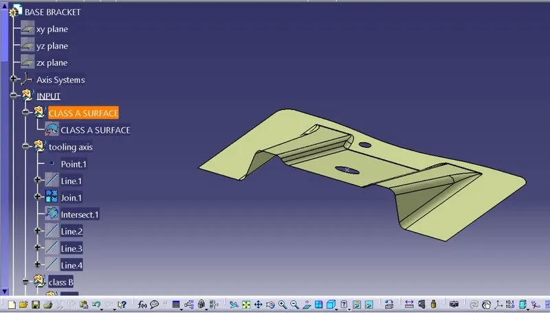
First, create a "tooling axis" for the part.
Place a point at the centre of the hole of the class-A surface. Insert a reference plane or an axis system by selecting the point.
Then use the line in reference elements and select the point as the input and the direction of the line is ZY plane.
We do not know whether this reference which we created is the exact tooling direction for the component. So we use another method called the “bisecting method”.
In this method, we use the axis system to create and use the intersect command by selecting the surface. We’ll get a continuous line that runs across the surface.
Now, we use the reference element line and draw two lines by selecting the two edges of the class-A surface. Using the line command and selecting the option ‘bisecting’ method we select the two lines as a reference and the point as the origin for the line that has to be formed. Using these two lines and the point, the tooling axis is created. The bisecting method actually bisects the two reference lines and draws a line from the intersection point of both the reference lines.
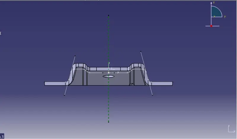
After we get the tooling axis, we need to create a Class-B surface. Class-B surface is the surface that is at the offset distance of 3mm. In simple words, it is the base that we create.
Now to create this class-B surface we mainly use extract, untrim, extrapolate, trim and offset options. First, we select the base surface, extract it, untrim the sheet, extrapolate it to a certain mm, say 10mm and hide it. Later we’ll use it for trimming operations.
Similarly, we extract the two curved surfaces of class-A, untrim them, extrapolate the sheet to 10mm and use the trim operation to get the desired shape.
After trimming we need to offset all these trimmed parts to a distance of 3mm. Now trim the offset parts with the base surface which we have previously hidden. We also need to offset this base surface to a distance of 3mm. And now trim all these surfaces, we’ll get our class-B surface.
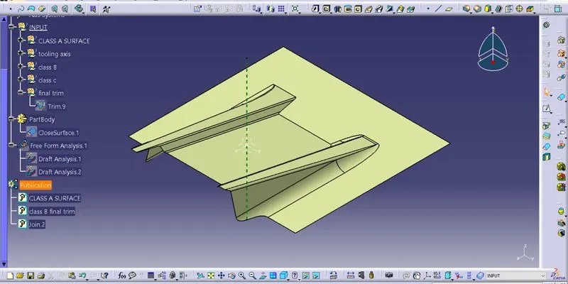
To join the class-A surface and the class-B surface we need to fill the region in between the two surfaces. The creation of this region is called Class-C surface.
In creating the class-C surface we use the class-A surface and extract the boundary of the class-A surface. Using this boundary we use the sweep command and with an angle of 3deg, we generate a surface perpendicular to the boundary of the class-A surface. And for the holes perform the same operation. Select the boundary, select sweep, give the draft angle and choose the direction of the draft.
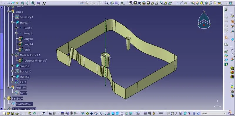
After creating this class-C surface, join the class-A surface with the class-C surface. Now we need to unhide the class=B surface and select trim operation. Using trim, we remove the excess part of the class-C surface and we get our required product of 3mm thickness.
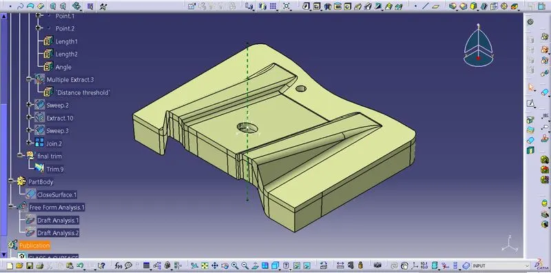
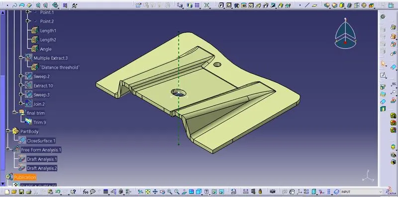
Now using the part body, use insert the closed body option and get the final output.
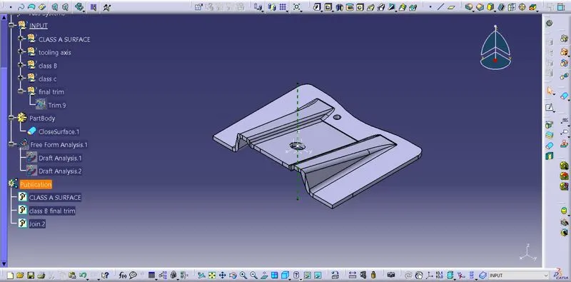
Draft analysis of the class-A surface.
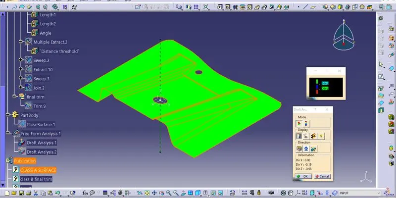
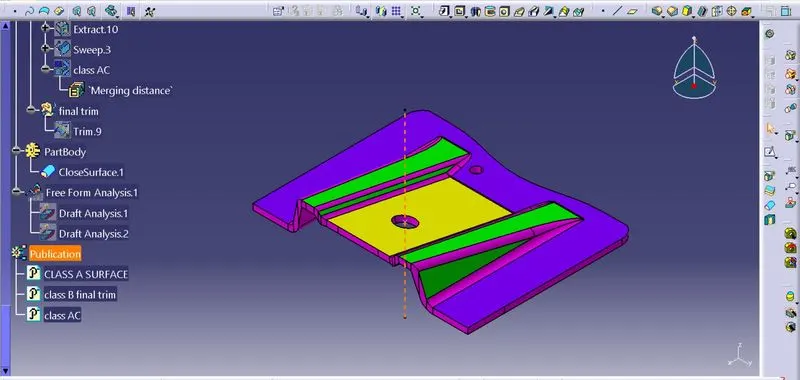
Draft analysis of created part with 3mm thickness.
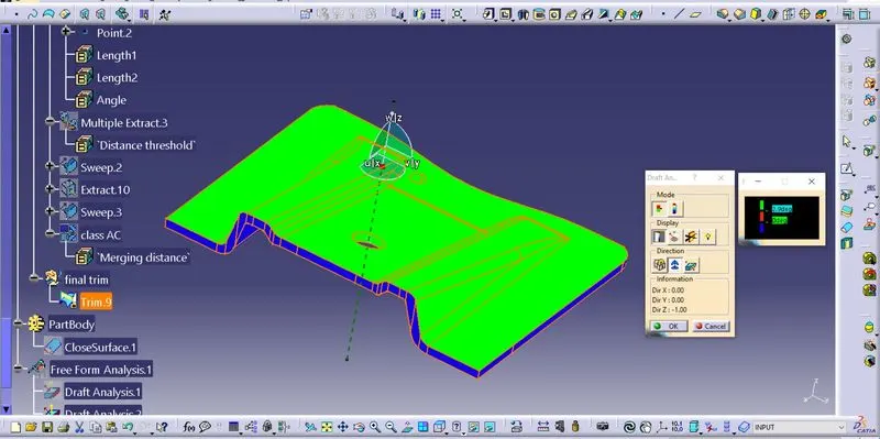
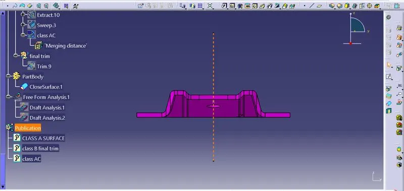
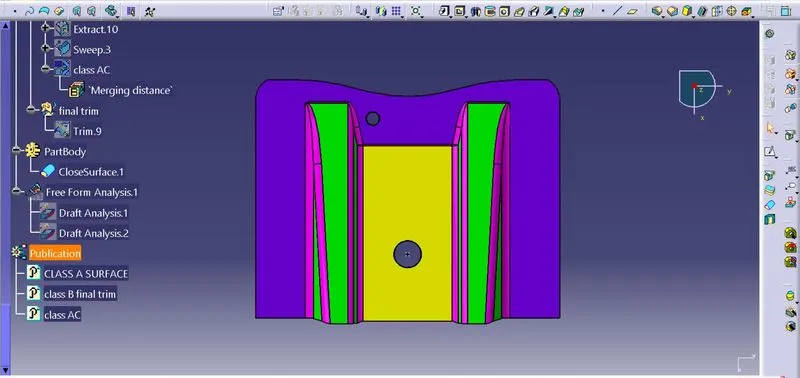
- Screenshots of the solid model with the proper colour code of the draft angle in various orientations (Isometric, Front, Side, and Top View).
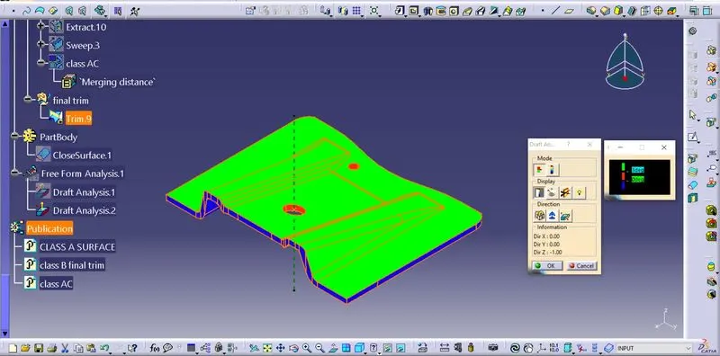
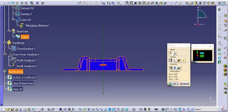
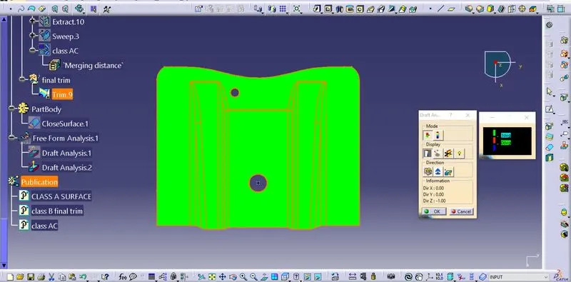
The region which shows green satisfies the draft angle and the part can be easily ejected.
The region which is in blue colour at the bottom is considerable and can get into the green region by adjusting the draft angle.
The region that is red colour is not considerable and should be modified using the draft angle. In this model 3 deg draft angle is provided. To make the circular cut-outs and little modification is done to the draft angle. From 3deg we reduced it to 2.9 degrees. Then the circular cut-outs changed into green colour. so the optimum draft angle for the whole part is 2.9deg.
comparison of draft analysis on the class-A surface and final product.
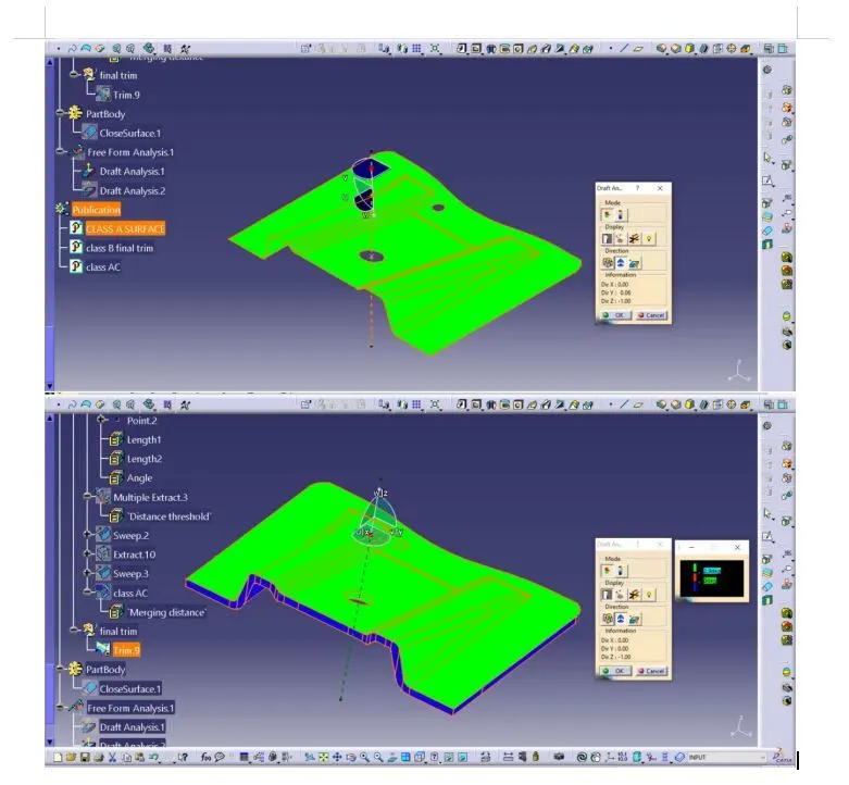
Images of the solid body.
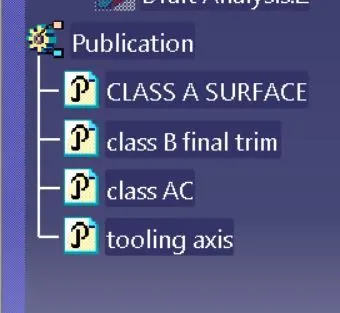
- Publications: Use the publication option and publish the below
- Tooling Axis
- Class A, B, and C surface