Week 8 - Challenge 1 - Base Bracket Design
BASE BRACKET DESIGN
AIM :
T create the class B and class C surfaces fron the given class A surface, and performing the draft analysis on the given class A surface and the final componenent .
Objectives :
- Creation of class A and class B surface .
- Creation of tooling axis .
- Performing the draft analysis.
- Convert the solid model from the surfaces .
Tooling direction
tooling direction is basically that the direction that mold pulls apart from the mold . Generally the molding machine have the two portions they are core and cavity. The core is the fixed part and tye cavity is the moveable part . The moving direction of the cavity is called tolimg direction.
Procedure for creating the tooling axis
AT starting the dummy tooling direction is created on the point of hole center .
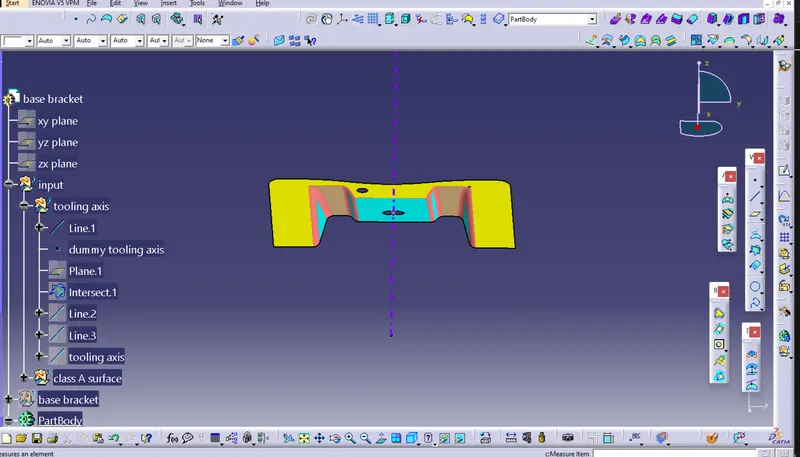
Then one datum plane is created on at the center point of the to hole .
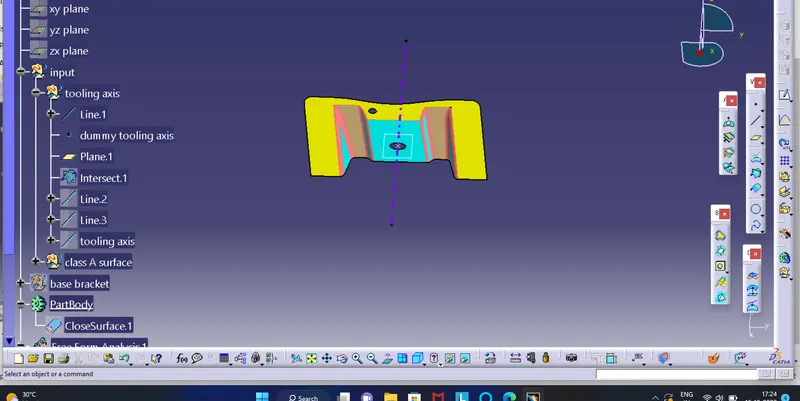
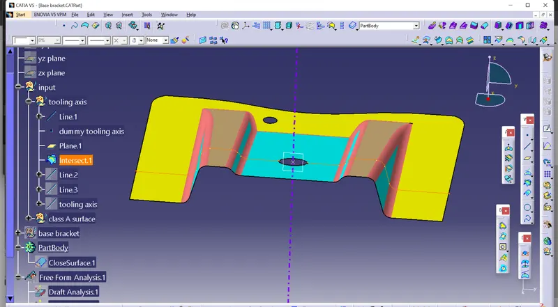
After that the intersection is created between the datum plane and to the surface .
After that two side lines are created where the tooling will be crtical. Then creating the bisecting line between them ,the tooling axis is created .
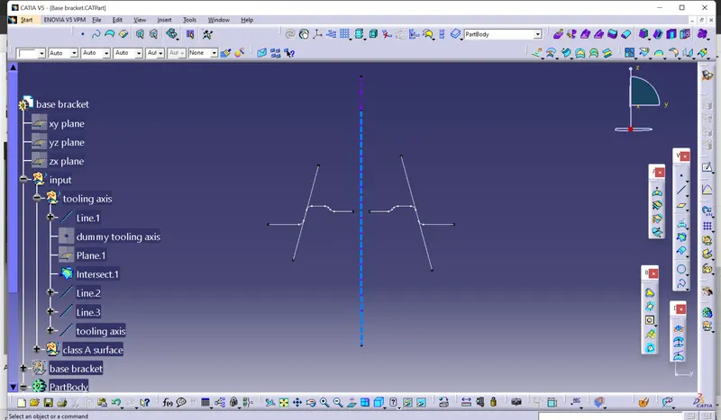
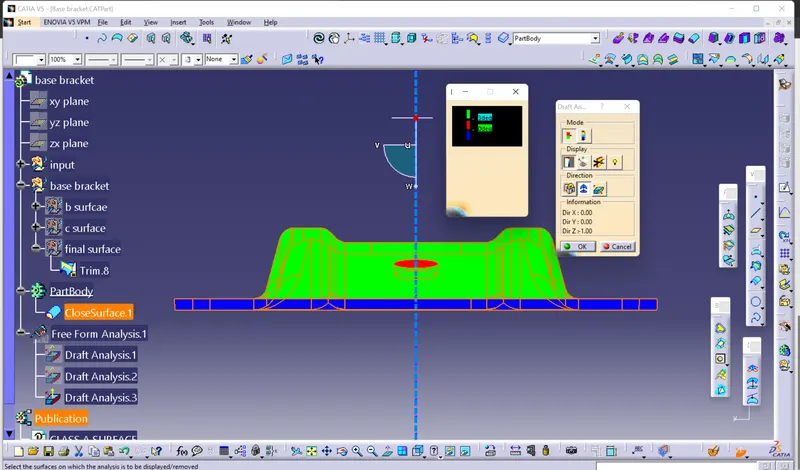
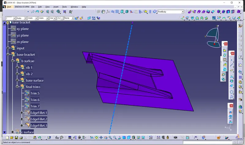
( Here the center dotted line is our tooling direction )
Draft analysis
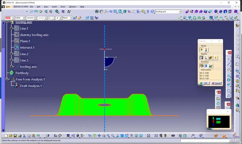
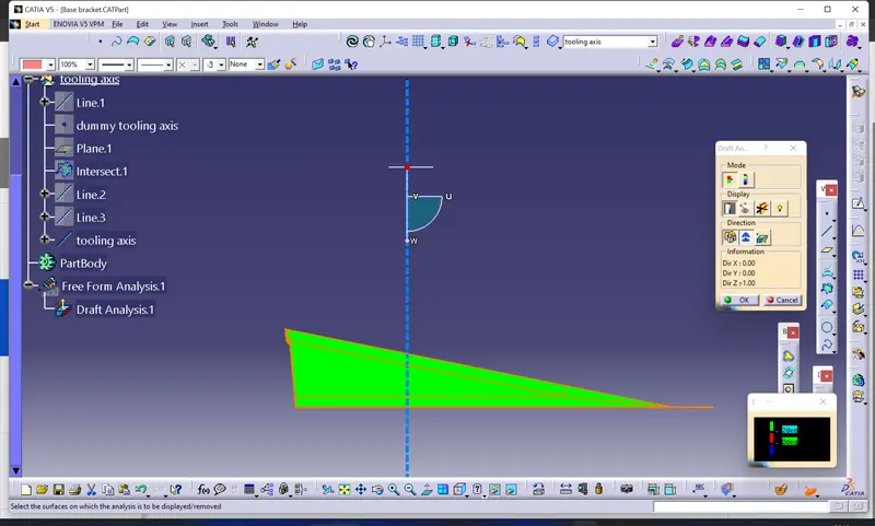
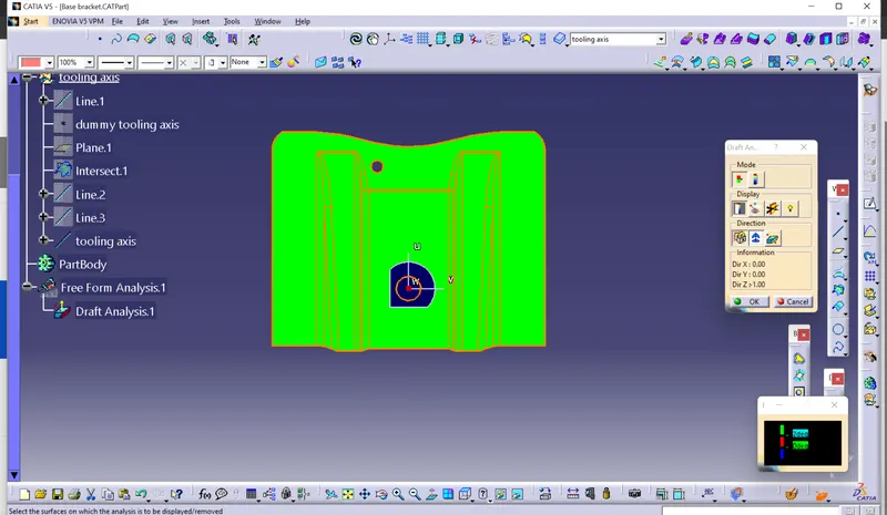
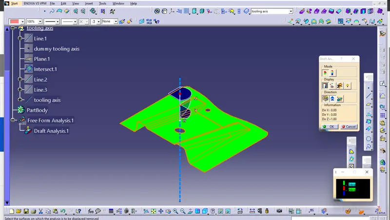
The draft analysis technique is used to analyse the created part model design is manufacturable based on the draft condition applied . Here the part should be easily removed from the mold . No parts can be easily ejected from the mold if it has 90 degree profile from its base surface . The small draft angle is provided on the each and every area of the component for easy removal of the component from the mold.
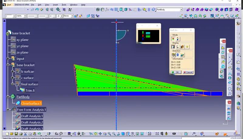
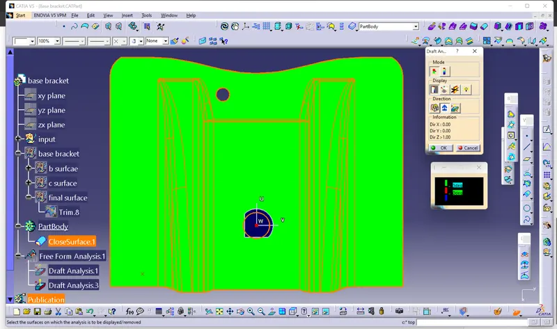
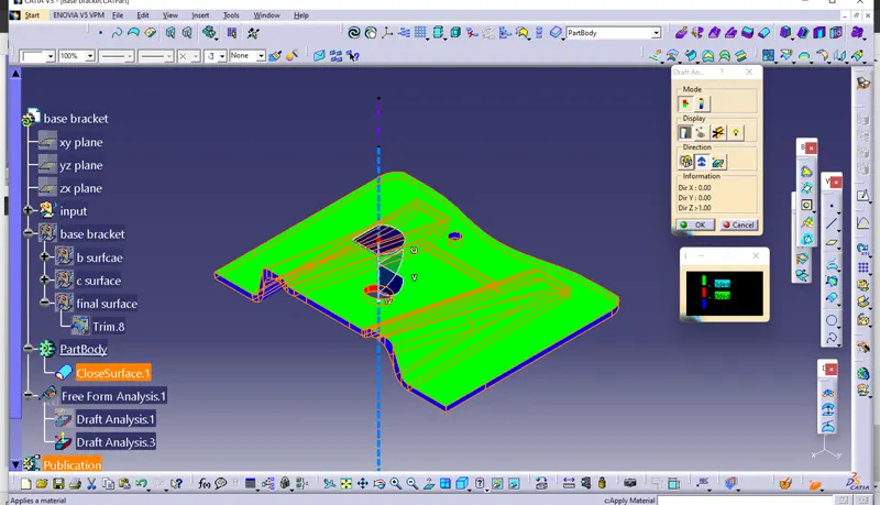
Draft analysis on class A surface
Draft analysis on the final component
Class B surface
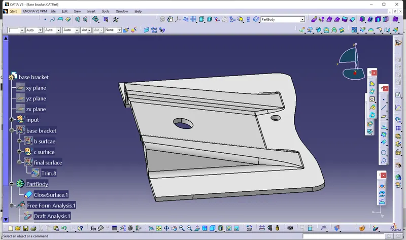
( In this surface 2.5 mm takened as the thicnkess of the component)
Class C surface
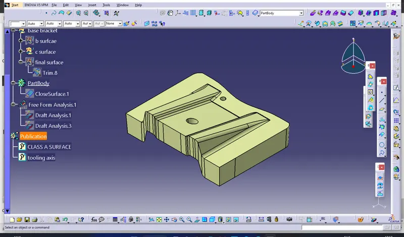
Final component
conclusion
The calss B and class C surfaces were created from the given class A surface . Then the tooling direction is created and the draft analysis is performed on the both class A and final product .