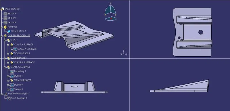
Week 8 - Challenge 1 - Base Bracket Design
OBJECTIVE
Create the Base Bracket Plastic component through the given Class-A surface and perform draft analysis.
PROCEDURE
- Creation of Tooling Axis
- Perform Draft analysis of Class A surface
- Creation of Class B and Class C surface
- Create the solid surface
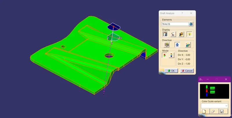
- Perform Draft analysis of Solid Surface
CLASS A SURFACE
Class A surface mean the surface of a component which is smooth or visible side to human eye after the part is assembled. It is refers as the aesthetic surface of a Vehicle.
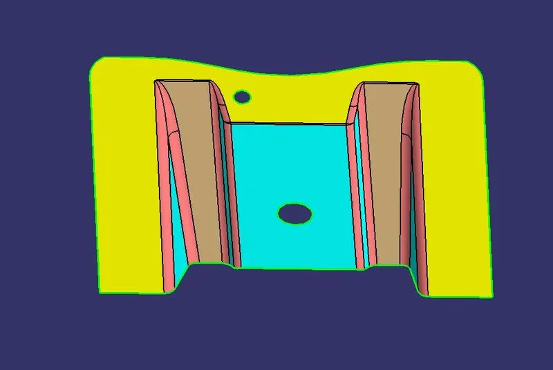
TOOLING AXIS
Tooling axis is the direction in which the mold and cavity opens and closes in the injection molding operation.
PROCEDURE TO CREATE TOOLING AXIS:-
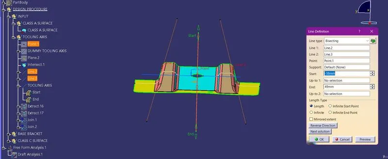
1- Create an intersection line of Class A surface
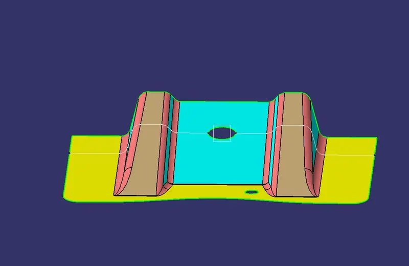
2- Create 2 line by from the intersection line as shown in the image
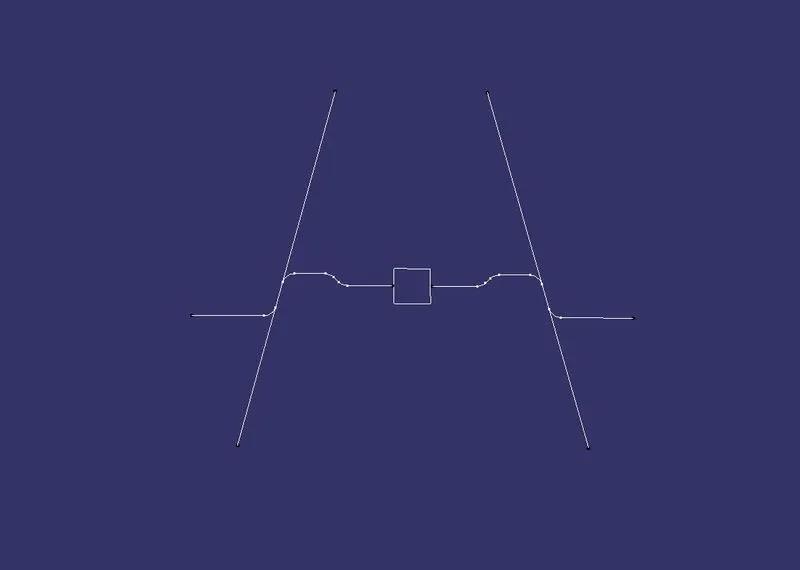
3- Create a bisecting line by using these 2 lines and the center point and this bisecting line is the tooling axis for this operation
CREATION OF CLASS B SURAFACE
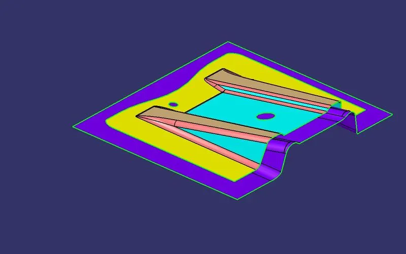
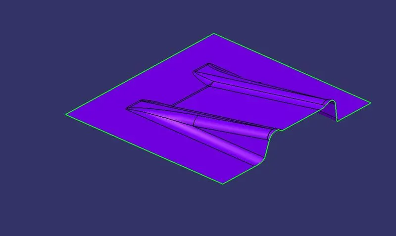
Class B surface is used for Engineering purpose. All the design parameter are done on the Class B surface.
PROCEDURE TO CREATE CLASS B SURFACE:-
1- We have extracted major faces from class A and offset it by 2.5 mm
2- We untrim and Extrapolate those faces
3- We have trimmed those faces as our required shape and gave fillets to make the surface smooth
CREATION OF CLASS C SURFACE
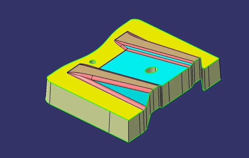
Class C surface is used to join the Class A and Class B surface together.
PROCEDURE TO CREATE CLASS C SURFACE:-
1- To obtain Class C surface we have to extract the boundry of Class A surface
2- We have used sweep command with 3deg draft
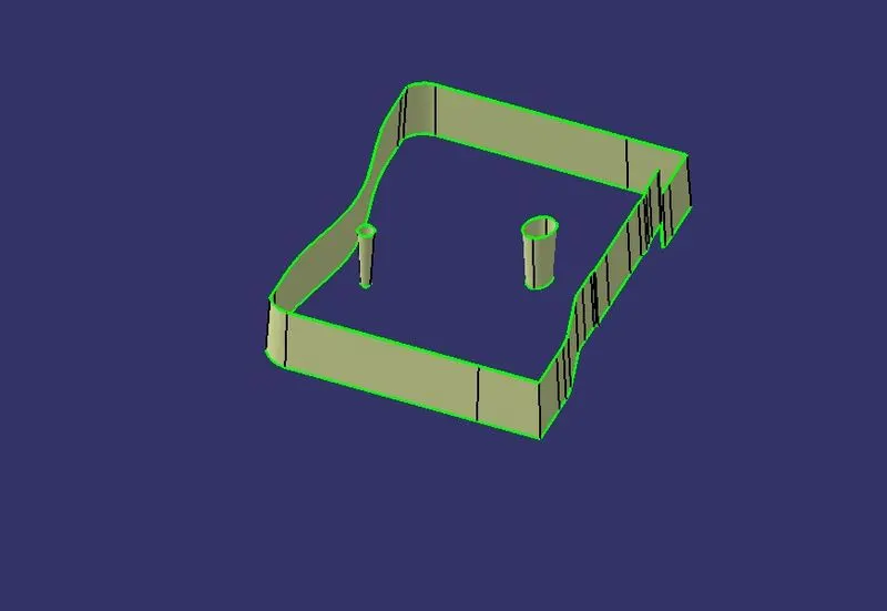
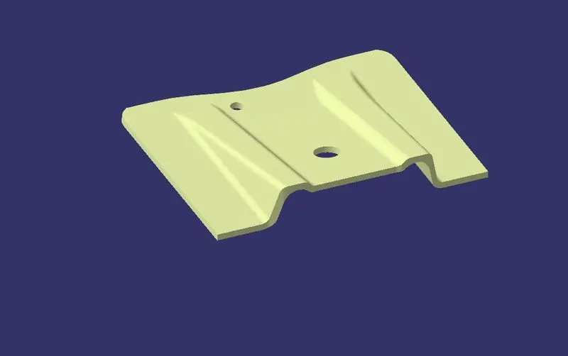
3- We trimmed Class A, Class B and Class C together to create the final product
DRAFT ANALYSIS
Draft analysis is done to know wheather the part will be easily manufacturable by the given draft angle or not. It will ensure that the part will not stuck in the core and cavity.
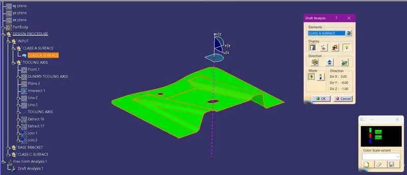
PROCEDURE TO PERFORM DRAFT ANALYSIS:-
- Right Click on Tab < Go to Analysis < Feature Draft analysis
- Put the View Mode in material option
- Align the compass with the tooling direction line
- The surface will turn into green colour it means the part is manufacturable with the given draft angle.
SOLID SURFACE