Week 8 - Challenge 1 - Base Bracket Design
AIM: Create the Base Bracket Plastic component through the given Class-A surface
OBJECTIVE:
- Creation of tooling axis
- Draft analysis of Class-A surface
- Creation of Class-B and Class-C from the Class-A surface using all design standards
- Creation of solid part out of the surface model
- Draft analysis of the final plastic component.
INTRODUCTION:
In this project, we are designing base bracket plastic components through a given Class-A surface using the Catia software, from that we create a Class-B surface with a thickness of 2.5 mm throughout the component. And Class C is also created using both Class A & B. Draft analysis is also conducted with a minimum of 3 degrees as standard. Make sure that the surface model is completely closed before converting into solid.
Draft
In engineering, draft is the amount of taper for molded or cast parts perpendicular to the parting line. It can be measured in degrees or mm/mm (in/in)
- Drafts (or taper) in a mold, facilitate part removal from the mold. The amount of draft angle depends on the depth of the part in the mold, and its required end-use function.
- The draft is in the offset angle in a direction parallel to the mold opening and closing.
- It is best to allow for as much draft as possible for easy release from the mold. The minimum taper angle is 0.5 to 1 degree but 3 degrees is a widely accepted norm.
- The mold parting line can be relocated to split the draft in order to minimize it. If no draft is acceptable due to design considerations, then a side action may be required at a greater expense in tooling.
Draft Analysis
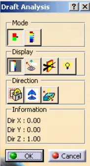
Displays a color gradient on the faces of selected bodies to help evaluate the manufacturability of your design. Select the bodies to evaluate and the axis to define the direction. Use the options to refine the gradient display. In Catia, we use the feature draft analysis tool for this.
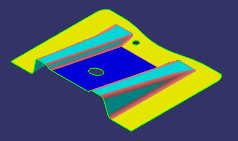
Class-A
This Class-A surface is given as input.
PROCEDURES
Step 1 - Make the tooling axis
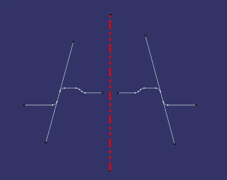
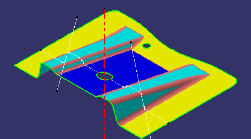
The first process is to find the tooling axis for that we use the bisector method. In this problem, we select hollow circle as a reference by creating a center point. Then, create an intersection curve with respect to a plane (reference as yz plane) then create lines corresponding to the draft then make a bisector with respect to the lines ie, tooling axis.
Note: Select the face which feels that will make a problem for tooling.
Step 2 - Draft Analysis of the Class-A Surface
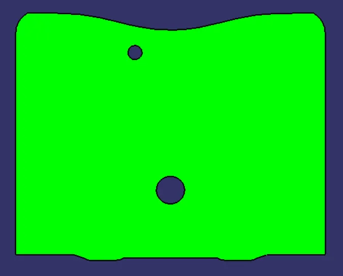
Draft analysis is conducted with a limiting value of 3 degrees.
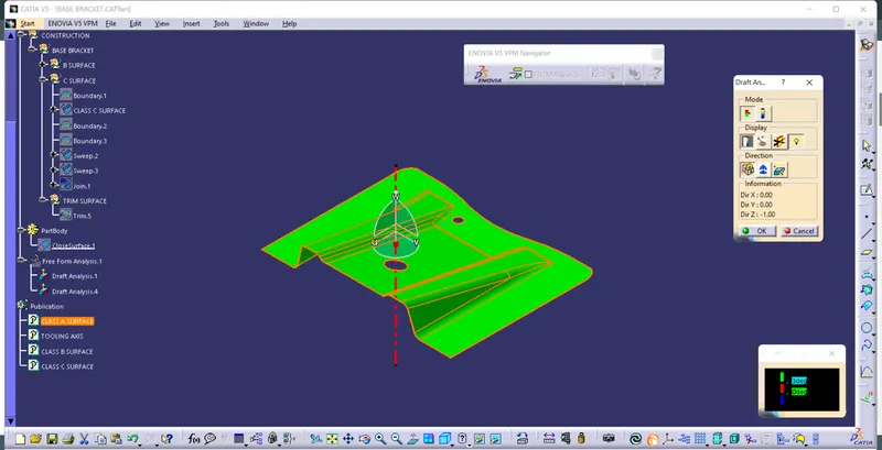
Color Scale used:
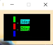
The green color indicates the draft angle is more than 3 degrees
Step 3 - Creation of Class-B Surface
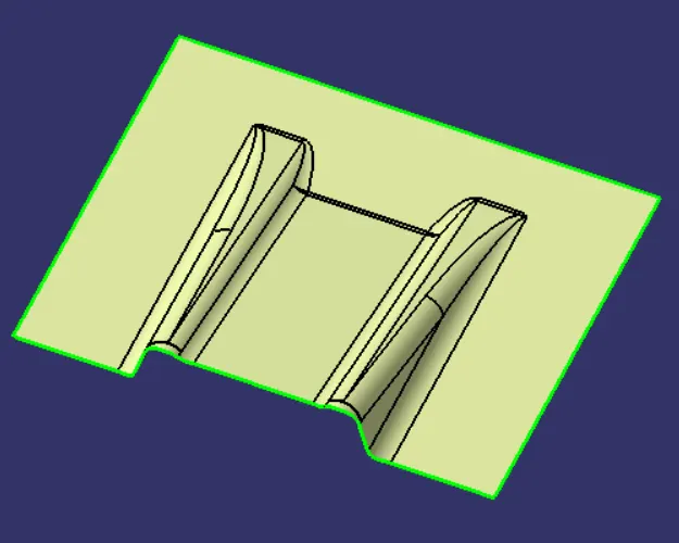
In this, the Class-A surface is extracted and then untrim it. Then offset to 2.5 mm and extrapolate all edges to 10 mm along the surface direction. Do this process for each rib and base surface separately then trim all the into a single B Surface.
Then give the required fillet. (fillet radius + thickness)
Step 4 - Creation of Class-C Surface
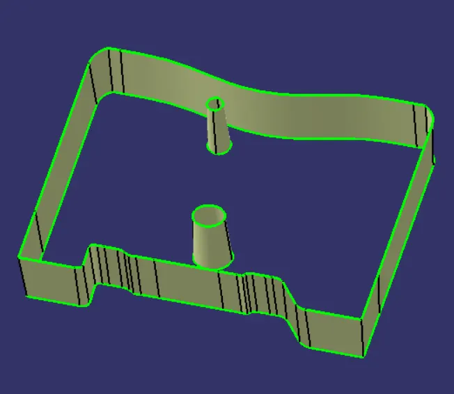
Class C Surface is the connection surface of Class-A and B. For this make boundary for the Class-A Surface then extend it along the tooling axis direction with a draft angle of 3 degrees using the sweep command. Same for both holes in the Clas-A Surface as shown below.
Step 5 - Final Trim:
Class-A + Class-C
In this, we connect both Class-A and C with the join command and make sure there is no gap between A & C.
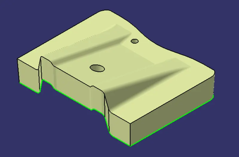
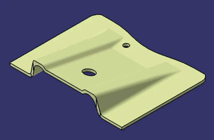
Class-A + Class-B + Class-C
This made the final output from the surface workbench by trimming all the unnecessary portions and check the surface is completely closed.
Step 6 - Draft Analysis of Final Plastic Component
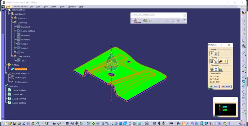
Color Scale used:
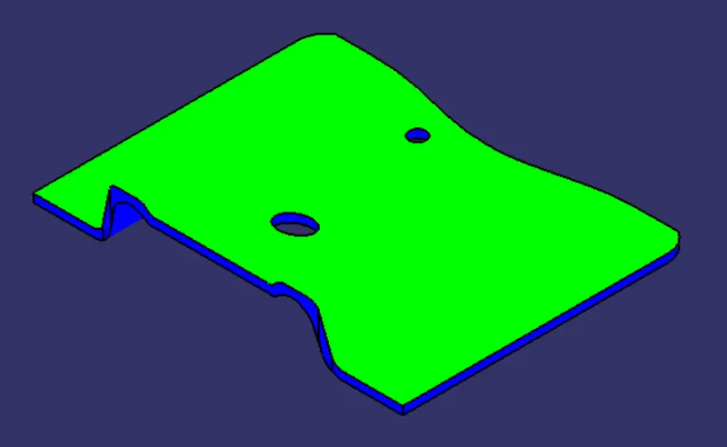
Draft above 3 degrees is shown as green.
CONCLUSION
- Tooling axis created
- Draft analysis of Class-A surface is conducted
- Class-B and Class-C are created from the Class-A surface using all design standards
- Solid part is created out of the surface model
- Draft analysis of the final plastic component is conducted.
1. Isometric View
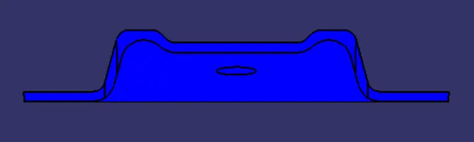
2. Front View
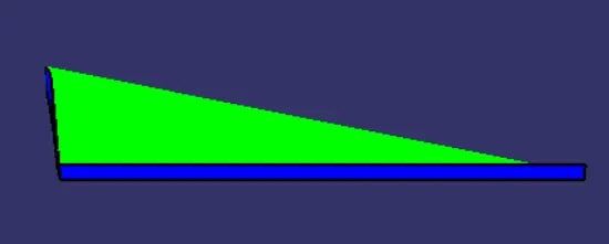
3. Side View
4. Top View