Week 8 - Challenge 1 - Base Bracket Design
AIM: Create the Base Bracket Plastic component through the given Class-A surface. Begin with, the tooling axis for the given Class-A Surface should be created meeting the requirements of the draft angle and at the end perform the Draft analysis on the given plastic model.
TOOL USED : CATIA V5
NOTE:
- Tree Structure Ensure Proper Tree Structure
- Geometrical sets should have a proper name based on the sketches present inside of it
- All the sketches should be created under the Geometrical set
- Use the Close Surface feature to make a solid body from the surface.
- Publications: Use the publication option and publish the below.
REPORT-
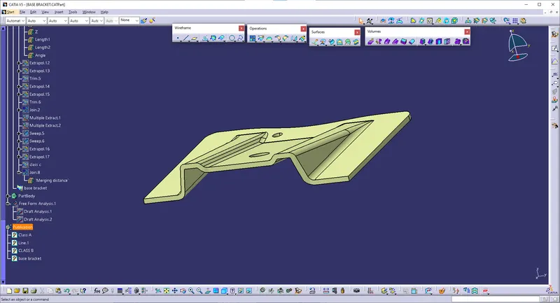
INTRODUCTION:In this project we are designing a base bracket using given class A surface. IT includes creation of Class B surface keeping 3 mm thickness in mind for the complete component. The design also included Class C creation from the given parent surface.
OBJECTIVES :
- Creation of Tooling Axis.
- Creation of Class B and Class C surface.
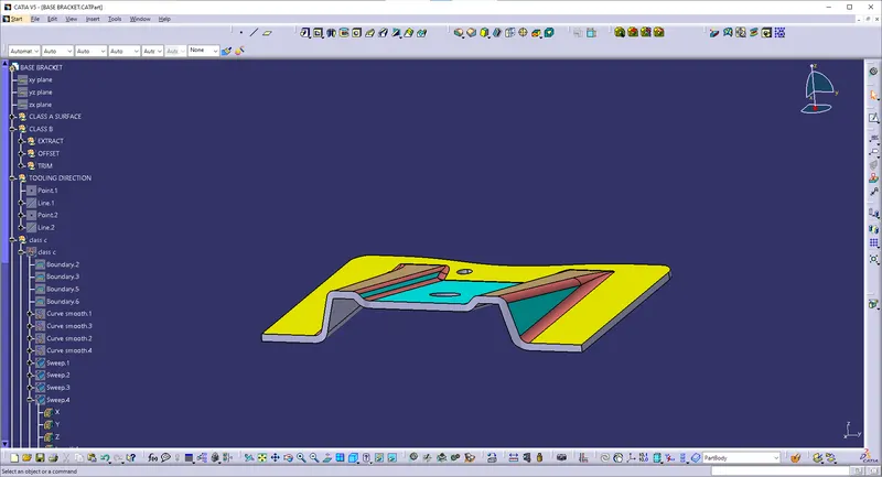
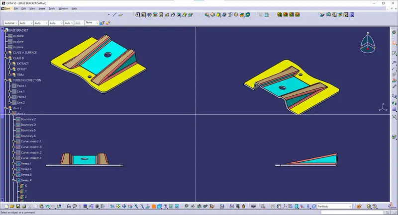
- Creating a solid part out of surfacemodeling.
- Draft Analysis of Class A surface and final plastic component.
TOOLING AXIS: we should study the given class A surface to create the tooling axis for the component. for the given base bracket z-axis is best
suited axis .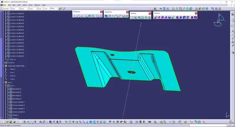
DRAFT ANALYSIS:
Draft Analysis is a tool in CATIA which identifies the zones which deviates from the specified values of angles along a defined draft direction using colour codes.
It highlights the regions of draft using colours. Draft analysis is the first step performed after receiving the Class A of the component. 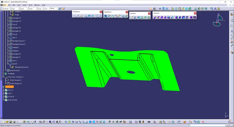
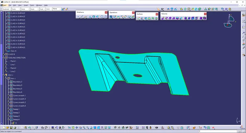
CLASS A :In automotive design, a class A surface is any of a set of freeform surfaces of high efficiency and quality. It is the visible aesthetic surface of any automotive component. Class A surface refers to those surfaces which are visible and abide to the physical meaning, in a product. This classification is primarily used in the automotive and increasingly in consumer goods industry. It is a requirement where aesthetics has a significant contribution. For this reason, the exterior of automobiles is deemed Class-A.CLASS A surface is already given to us . it should not be altered or changed .
CLASS B :
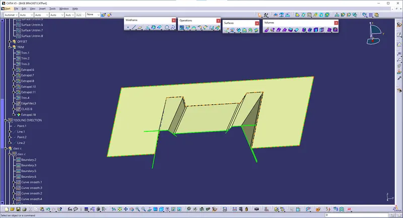
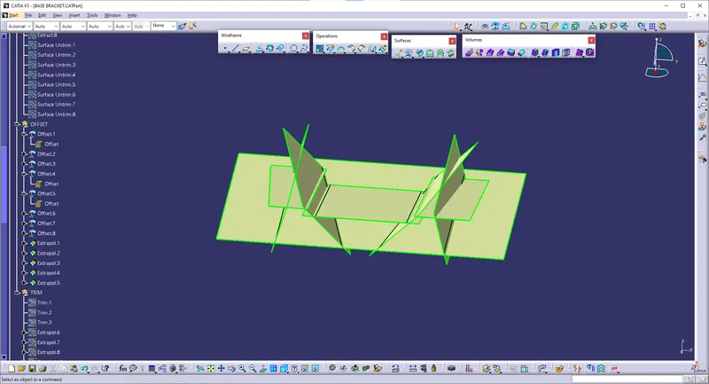
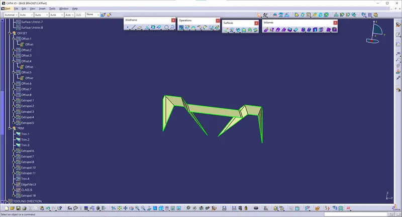
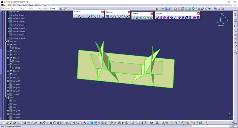
- To create the class B surface, I considered the entire surface has 3 parts 'Rib-1, Rib-2, and Base surface.
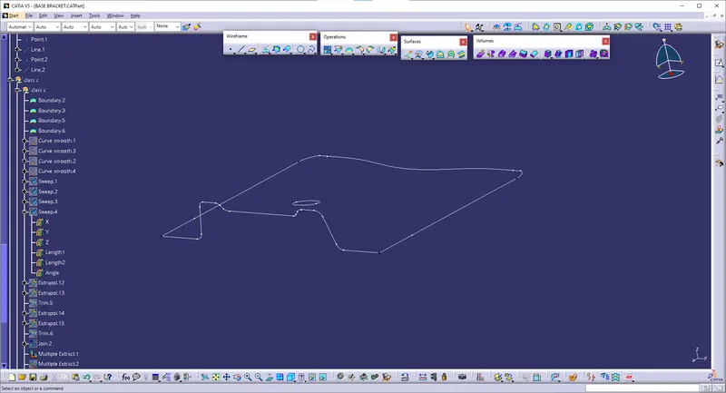
- If we directly offset the class A surface, fillets may lead to cause an error, to avoid the errors we need to extract the surfaces and untrim the extracted surfaces and extrapolate those untrimmed surfaces with point continuity.
-
Now trim those extrapolated surfaces to the required shape. And finally, fillets were given to the final trim.
CLASS C:
- It is the combination of Class A, Class B and Class C surfaces.
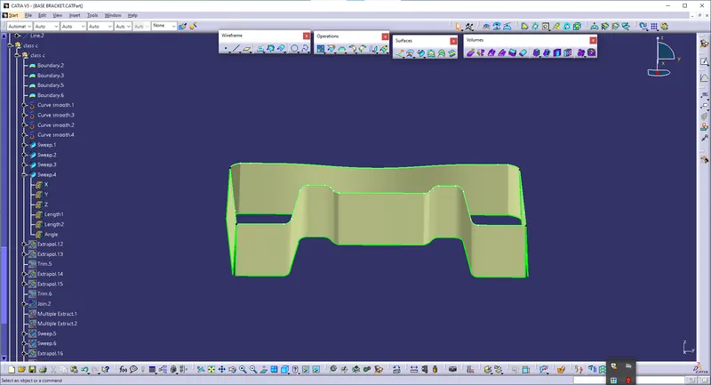
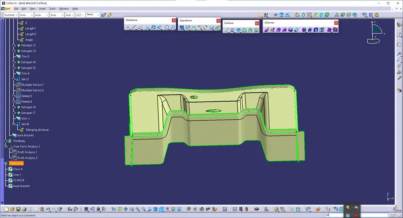
- To create a class C surface, I used the sweep command by considering the outer boundary of the class A surface.
- In the sweep command, go to the 'line' command in the 'profile' block and the subtype is 'with draft direction'.
- Now select the outer boundary and tooling axis, give 3 deg in the angle (the draft angle for a plastic component is 0.5 to 3 deg) and select the direction to sweep, in this condition the class B surface is under the class A surface so select the inside down arrow to sweep.
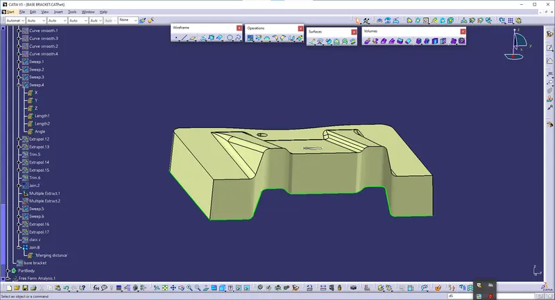
- The same procedure is repeated for the two circles on the class A surface. Now I joined all the sweeped surfaces by using the 'join' command and then I trimmed the Class A, Class B and Class C surfaces to make a closed surface, to make a Solid body.
OPERATION'S:
- BOUNDARY
- SWEEP
- SMOOTH CURVE'S
- EXTRAPOL
- TRIM
- MULTIPLE EXTRACT
- JOIN
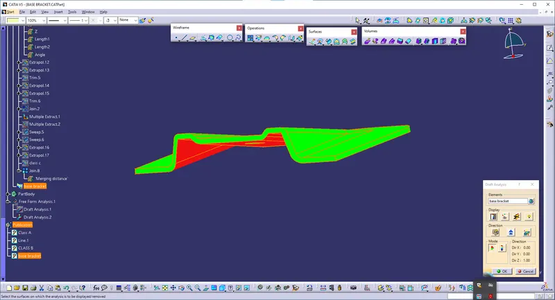
DRAFT ANALYSIS OF CLASS C:
For this analysis, main tooling axis is taken draft reference.
Following results were obtained:
SOLID-BODY:
CONCLUSION:
The Design of Plastic Component - Base Bracket from Class A is completed using concepts of Draft angle, Draft Analysis, Tooling Axis, Class B and Class C creation and converting Closed surface to a solid part.