Week 9 - Attachment Feature Creation (Ribs & Screw Boss) - Challenge 1
Objective-
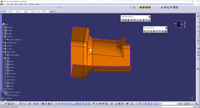
To Create the Attachment Features (Ribs & Screw Boss) on A Door Handle through the given Class-A surface by creating tooling direction, the tooling axis for the given Class-A Surface should meet the requirements of the draft angle i.e. minimum 3°and at the end to perform the Draft analysis on the model.
REPORT-
CONSIDERATION :
- Class – A surface should be aesthetically smooth
- Class – B surface should have all the supporting features like ribs.
- Parting Line should coincide with the B surface since flashing couldn’t affect the aesthetic of Class – A.
- Class – C surface should also pass the draft analysis.
- and creation of ribs and screw bosses
Objective:
- Geometrical sets should have a proper name based on the sketches present inside them.
- All the sketches should be created under the Geometrical set.
- Use the CLOSE SURFACE feature to make a solid body from the surface.
- To publish the Tooling Axis, Class A, B, and C surface.
- Ensure Proper Tree Structure
CLASS A SURFACE:
- Go to insert- analysis- feature draft analysis
- Align the tooling axis with the compass.
- Click on the surface and see that the surface is within the permissible limit of the draft values.
- The surface should be green and in the column nominal value 2.5deg given as input. hence the draft analysis on the class-A surface is successfully performed.
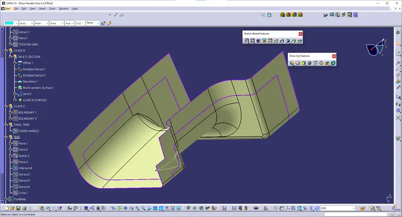
CLASS B SURFACE:
- For creating the class-B surface the required surface except the offset surface have been extracted and then untrimmed all the surface.
- Then all the surfaces have been extrapolated to get intersections between them.
- Since the thickness of the coin holder is 2.5mm the B-Surface was offset to 2.5 mm and the required trim operations must be carried out.
operations:
- extract
- untrim
- offset
- extrapol
- multiple extract
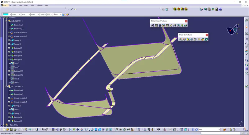
Class C SURFACE:
- It is the combination of Class A, Class B and Class C surfaces.
- To create a class C surface, I used the sweep command by considering the outer boundary of the class A surface.
- In the sweep command, go to the 'line' command in the 'profile' block and the subtype is 'with draft direction'.
- Now select the outer boundary and tooling axis, give 90 deg in the angle and select the direction to sweep, in this condition the class B surface is under the class A surface so select the inside down arrow to sweep.
- The same procedure is repeated for the two circles on the class A surface. Now I joined all the sweeped surfaces by using the 'join' command and then I trimmed the Class A, Class B and Class C surfaces to make a closed surface, to make a Solid body.
OPERATION'S:
- BOUNDARY
- SWEEP
- SMOOTH CURVE'S
- EXTRAPOL
- TRIM
- MULTIPLE EXTRACT
- JOIN
Ribs and Bosses Design Guidelines in Plastic Parts-
Ribs-
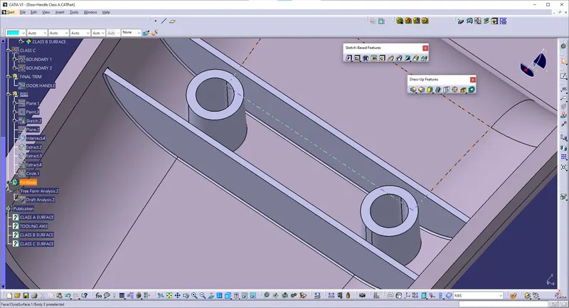
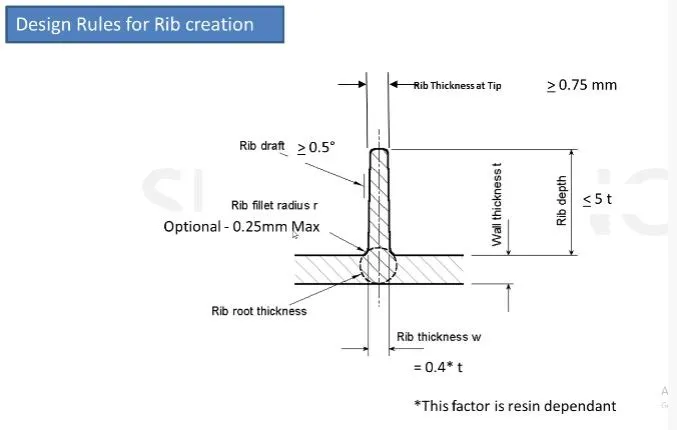
Ribs are indispensable functional structures on many plastic parts. It can effectively improve the rigidity and strength of plastic parts like the H beam.
Ribs are generally designed on the non-appearing surface of the plastic part, and its direction is as close as possible to the flow direction of plastic melt filling. Ribs should neither be too long nor too thick, otherwise, it will increase the difficulty of injection moulding, causing problems such as voids and sink marks on the back.
Bosses-
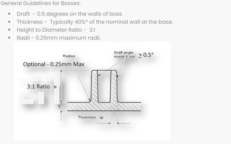
Bosses are common structures on plastic parts in home appliances and interior and exterior of auto-mobiles, mainly for positioning and fastening.
The base of bosses often cause sink marks on the back surface of a part, this is because of the large wall thickness. The solution is to core out some material at the base.
tooling axis:
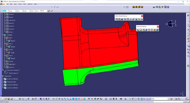
For this analysis, main tooling axis is taken draft reference.
Following results were obtained:
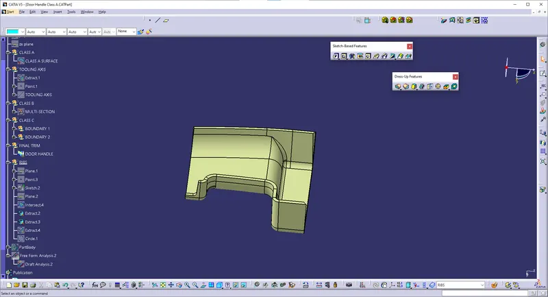
solid part:
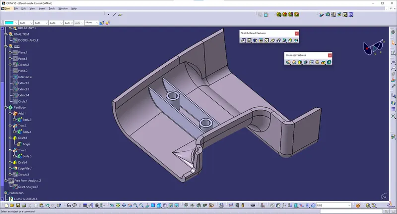
CONCLUSION:
The Design of Plastic Component - from Class A is completed using concepts of Draft angle, Draft Analysis, Tooling Axis, Class B and Class C creation and converting Closed surface to a solid part.